

Learn about the GrabCAD Platform
Get to know GrabCAD as an open software platform for Additive Manufacturing
Visit our new homepage
Show off your skills and solve real design problems

Tern needs your help optimizing a crank to reduce the weight. The goal is to maintain strength and design features.
All the entries have to be private and shared access to joakim.uimonen@ternbicycles.com and kaspar@grabcad.com
To get the specification send an e-mail to kaspar@grabcad.com and we will send you the NDA with the CAD files.
There are two cranks which need to be optimized: Right side crank with 5 bolt star shape Chain ring mounts and more simple left side crank.
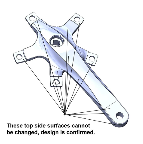
Current looks are well appreciated, so front sides of the cranks should stay like they are. Rear side and sides of the crank can be revised.
New forging tooling can be opened for both of these cranks.
Crank is under quite a stress while cyclist is pedaling hard. So the crank need to be safe enough to withstand the stresses of pedaling.
Current cranks are strong enough, but too heavy. This leads to the main problem- “How much and where can we safely reduce material for weight savings without compromising the strentght?”
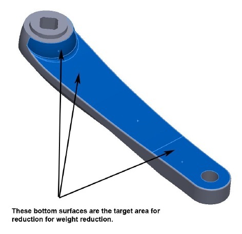
Rear side of the crank arms are aim for the modifications. See blue shaded surfaces in the images. Reference surfaces are added as 3D files for reference. These bottom surfaces are the target area for reduction for weight reduction.
See example how the material can be reduced from the bottom side of the crank: Single cavity in the middle of the of the bottom side of left crank.


Durability after weight reduction and manufacturing possibility are the main concerns
As the crank rotates during the pedaling action the direction of max stresses also varies during the rotation.
Crank durability requirements are listed in CEN standard. And as this crank is used in City bikes it must comply with requirements from:
CEN, EUROPEAN STANDARD EN 14764
City and trekking bicycles - Safety requirements and test methods
Especially sections:
4.13.6 Drive-system — Static strength test
Consider the assembly to be single speed system
4.13.7 Crank assembly — Fatigue test
See test requirement details in attached section of CEN standard.
Cranks are made with cold forging process, so the new shapes in the rear side need to be produce able in forging process
All surfaces need to have min draft of 3 degrees
Minimum radius in forged parts is R min 2mm
Max amount of separate cavities on rear side is 6 cavities
Min wall thickness is 4mm
Material is aluminum 6061.
Top side surfaces cannot be changed, top side design is frozen
Bottom and side surfaces can be revised for weight savings
Material can be reduced or added to the bottom side. Sides can be made thinner, as long as the top surfaces remain untouched
See 3D files of the base cranks
Lightest crank version that can be produced by forging and which passes the CEN EN 14764 crank durability requirements wins
Test results of FEM Durability analyze need to be shown together with the weight reduction result
All the entries have to be private and shared access to joakim.uimonen@ternbicycles.com and kaspar@grabcad.com
CAD files will be sent by kaspar@grabcad.com together with the NDA.
Team entries are welcome. In case of team win, prize will be transferred to team leader who is solely responsible for splitting it among team members
Design can be made in any software as long as IGES file is provided.
Only models uploaded to GrabCAD library will participate in the competition
Only models uploaded through this challenge page here will participate in the competition
Tag your model with “terncrank” to make it easier to find
Weight reduction is the aim, but looks cannot be left out completely. If there are two competing suggesting in closely matching weight reduction result the better looking version wins. Tern design team will be authority to judge the looks.
Competition winner will be announced in GrabCAD’s blog and will be chosen based on the rules
Verge Duo for the winner. Worth 999 USD. http://www.ternbicycles.com/bikes/verge-duo
GrabCAD motivation package
GrabCAD motivation package
GrabCAD motivation package
GrabCAD motivation package
GrabCAD motivation package
The winner will be selected by a joint jury of Tern Bicycles and GrabCAD and announced on the GrabCAD blog.

Tern is dedicated to the goal of sustainable transportation. It designs and manufactures bicycles for urban transport with a focus on portability and utility. Tern donates at least 1% of net profits every year to social and environmental causes.

If you don't receive the email within an hour (and you've checked your Spam folder), email us as confirmation@grabcad.com

81 comments
Martin Camirand almost 14 years ago
Hi there!
Nice challenge!
You mention: "Crank is under quite a stress while cyclist is pedaling hard. So the crank needs to be safe enough to withstand the stresses of pedaling."
Have you determine a precise force that the crank have to withstand, because this would certainly be a key factor do optimize properly the design.
Thanks!
Martin C.
Pierre almost 14 years ago
nice challenge !
Cemal Uslu almost 14 years ago
nice challenge! bur i suggest to add some other prizes to 2nd and 3rd places.. that will make the cahllenge more attractive for us, engineers.
btw can't wait to have some free time to work on it and find a new solution. ;)
Fateh MERRAD almost 14 years ago
another great competition on the site grabcad, i like it
I will try to win a free time to participate in this challenge :))
QAPGAN™ almost 14 years ago
Hi all.. Its a great challenge I like it but there is a some problem with the download specification... and only contains Solidworks file type. Can it possible add to STP/IGES or Catia format too?
Manolis Theofilos almost 14 years ago
Nice one. Has been some time since I have worked with EN Standards, so this will be a nice return.
Andrey Jasiukaitis almost 14 years ago
CEN, EUROPEAN STANDARD EN 14764
City and trekking bicycles - Safety requirements and test methods
http://grabcad.com/library/european-standard-en-14764
I hope this link will be useful to all.
Good luck to everyone!
Martin Camirand almost 14 years ago
Thanks Andrey ! This will be usefull !
Martin
Joel Anderson almost 14 years ago
Any chance somebody with a newer version of Solidworks could make a .step out of the specification files? Much appreciated
bkinvent almost 14 years ago
Hi Joel, I've just done it for you. Let me know if you encounter any problems.
Bruce Coats almost 14 years ago
Hmm
The bike industry is huge. So many crank arms out in the market as it is. Ranging from Titanium, Aluminum, aluminum raped in high meniscus Carbon fiber. to just carbon fiber. looks like trying to reinvent the wheel.
Just look up
FSA
forged 6061 aluminum arms for Road 705g
Shimano
Dura-Ace 7900 thin wall Hollow forged aluminum crank arm 690g to 705g
Race Face
Arms are ultra-high strength 7050 aluminum alloy 1150g
Shram
1-piece forged 7075 aluminum arm 850/790g
Look, I'm not trying to be negative here but, people/engineers get paid good cash to come up this stuff i.e. above products.
Tern Bicycles is looking for a lot but don't wont to pay for the work or get license right for some products already on the market.
Joel Anderson almost 14 years ago
Thanks bkinvent. The top face is missing on both models and I haven't been able to patch it well enough to get it back to a solid. Is it possible to save it in any other format? Would a parasolid format work? I have little experience in file format conversions
ALI ALDUBAISI almost 14 years ago
I don't see any CAD files, there is only a picture.
Kaspar Kiis almost 14 years ago
Sorry I had to delete two converted Tern models. We had some confidentiality issues with the client. If you like to have the files just send me a quick e-mail and I will send them to you together with NDA. Thank you for you understanding.
Joel Anderson almost 14 years ago
Kaspar, Would it be possible to get the client to supply the models in a neutral format for everybody? It doesn't really seem fair on those of us who don't have the latest version of SoidWorks. Thanks
Tom Martin almost 14 years ago
I concur with Joel, I have solidworks 2010 and would like to participate in this challenge. Thanks!
Ljubisa Jovic almost 14 years ago
What version of Solid Works files are in specifikation???
Joel Anderson almost 14 years ago
Not sure Ljubisa. But 2010 wont open it so it's either 2011 or 12
Danny Tasmakis almost 14 years ago
Can we show images Kaspar?
Ljubisa Jovic almost 14 years ago
Ok , I hope so it would be better send specification in STEP file. I hope so!
Kaspar Kiis almost 14 years ago
CAD files are available in the following formats now: .SLDPRT; .IGES; .STL, and .STP. Hope it is ok with all of you. Just send me an e-mail to kaspar@grabcad.com and I will send you the Specification package against NDA.
Kaspar Kiis almost 14 years ago
You can share the images. But you have to upload the CAD files privately and share an access to joakim.uimonen@ternbicycles.com and kaspar@grabcad.com That's all it is.
Maciej Borowicz almost 14 years ago
Oficial properties 6061 ? I use tensile yield strength 241 MPa, ultimate tensile strength 300 MPa.
Joakim Uimonen almost 14 years ago
Great to see such interest on this challenge.
Hope later files that Kaspar is proving are more compatible to your software?
For material values, please use Alloy 6061 T4.
Standard values from solidworks will do.
Elastic modulus 69000 N/mm^2
Shear modulus 26000 N/mm^2
Mass density 0.0027 g/mm^3
Tensile strength 240 N/mm^2
Yield strength 227.527 N/mm^2
Hardening factor (0.0-1.0; 0.0=isotropic; 1.0=kinematic) 8.5e-007 N/mm^2
Sorry for late speck detail.
Bruce,
It is easy to dismiss these types of contests as trying to get something for free, taking advantage of students, etc. However, it is not so easy for students, hobbyists, etc to get a hold of real world projects and the experience of working/competing at a level where the real world demands are this high AND that a product will actually be produced.
1. Following a winning entry in a contest such as this, and inexperienced designer could point to something physical, tangible, and on the market and say: "I had a hand in that."
2. The value of the bicycle and associated costs of running the contest are not that much cheaper than doing it ourselves, and in some cases, some contests the cost is actually higher to do it that way, with potentially poorer, meaning less-specific, results.
3. The results are not guaranteed to be useable as well, though everyone involved hopes they are, so the potential loss of the entire investment and prize is non-zero.
4. Finally, the contest is open to all, but not required for anyone. If someone objects and does not wish to participate they are free not to.
Good luck and may the best model win!
Robert Stein almost 14 years ago
Well, I just read that 6061-T4 should be used. I was really worried that even the original had a low safety factor (less than 0.5 with plain 6061 Alloy...)
Just with the replaced material, now the safety factor on my work grew suddenly from approximately the same as original to 2.48 :)
One thing remains unclear, though. The modified file tagging or naming. Should it be exactly the same or should the authors of modified files add some pre- or su-fix to the file(s)?
Robert Stein over 13 years ago
I also had to use IGS/STEP instead of SW, I'm also still with 2010. Had to patch and fix the files to be able to work on them, also found a few minor errors during work I had to fix (probably a result of errors on edges and faces) but I think it will be acceptable, even though I don't expect to win anything. The fact I had my hand on this is enough, I would like to see how my ideas got in comparison to others ;)
Kaspar Kiis over 13 years ago
Guys I added a picture showing how the model upload and sharing process should go (see above, next to crank pictures). Please make sure everything is done according to that.
So far I can say that there have been lot of interest in this challenge. So it going to be an interesting one with lot of entries. Keep on going:)
CCG over 13 years ago
Keep on going isn't good enough...the challenge is good...the details are good but the model isn't because most of us use SW2010 or other older versions and for good results for us and also for you we need the right format. Now i am lossing time to convert and it doesn't give me the assurance that the conversion is corect. Not mensioning the fact that i have to agree to everything that Bruce Coats said. You are asking to much for nothing. I will enter the challenge because i like to put myself to the test....but it isn't right.
enforce over 13 years ago
how can i turn the imported files into something useful ? I just cannot use them properly for anything. Im using sw2012, and after any manipulation some faces disappar and some edges are unselectable...
Robert Stein over 13 years ago
Well, I did what I thought I can do with the files I got. It's a challenge, and complaining and whining usually doesn't help :)
I'll probably will not win anything, but winning was never my primary goal. Accepting the challenge and participating was fun, fixing errors was the biggest challenge with SW2010 having only an imported body... I wish the best of luck to everyone who took the challenge ;)
Andre Rätsep over 13 years ago
Is there also any desirable safety factor requirements set or the crank just has to not fracture under the load?
Chris Duncan over 13 years ago
Bruce, You need to keep quite if you do not yet understand crowd sourcing. The value is there it is just not what you are accustomed to.
Crowd sourcing has huge potential but you have to realize how it works. The main thing being that many engineers are better than one. A small firm may only have one engineer and it is easy to get a too narrow focus, where you cannot see the forest for the trees. There is only one way to get a lot of input and stay within budget and that is with a forum like this.
You may look at it like all the entries put together should be paid but that's just not how it works. It is the chance for someone trying to break into the field. It is the chance for someone that has been in the field for a long time to keep their skills sharp or prove themselves comparatively. Nobody is forcing you to be here. It is a challenge you either rise to it or you do not. For the winner I think it's a pretty fair prize, it should not take more than 20 hrs for the winning design and that's pretty good pay especially for an entry level person.
All that said I think this challenge is near impossible to get significant weight savings without affecting the front face. If you take away from the back without taking away from the front the cross section profile is no longer symmetrical and rigidity drops significantly with only small amounts of weight savings.
Also I can understand the NDA aspect but it is going to have something of a downside if all the engineers cannot see what others are doing and participate in question and answer feedback sessions. A large part of the appeal of this whole forum is seeing what others are doing and having others see your work.
Chris Duncan over 13 years ago
The stress on a crank arm like this is in bending and in torsion. There is going to need to be a calculation to determine the ratio of bending to torsion and design accordingly. With a clip on pedal there is going to be more bending but with street shoes I am thinking it is going to be more torsion.
The need for torsional strength would best be handled with a tubular design but that is difficult if not impossible with forging and forging is the only way for this material type and volume to meet the specs.
Thinking a tapered segmented die that fits down the tubular center. It would have a central draw cable and the segments would be interlocking for maximum rigidity. After the stamping process the draw cable is released and the segments pulled out of the center axle hole one at a time.
You would think that a bike crank has been refined as much as possible but you never know what can happen. One example is the climbing caribiner. It has been going through constant change over the years and many thought that it had reached the pinnacle of strength to weight ratio. But then Wild Country made a two year effort of design and came up with a new forging process to leave everyone else behind.
http://www.wildcountry.co.uk/download/pictures/product_karabiners/helium_karabiner_product_image_01.jpg
Robert Stein over 13 years ago
Not that it matters now, but I'm in bicycle business for about twenty years now, and when we want to save on weight of the drivetrain, we simply select a lighter product. However, weight saving is a thing that our customers decide on. Having in mind that what I do is not a mass produced product, all the focus was on the vehicle frame itself (including corresponding custom made parts) , to get an ergonomic, extremely durable, low maintenance product that we can give NQA guarantee for ten years... Most of the customers have their own ideas about the parts they want to have, so, it ends up with every unit being customized in some way... There is also an interesting thing, our customers from US used to prefer lighter rigs, while in Europe, on every fair, 9 of 10 potential customers asked about suspension. Once we managed to talk in our US distributors to get at least one full suspended version to have for demo rides, we only get orders for full suspended models, regardless of the fact that it comes with weight penalty.
Of course, there is no comparison here, a recumbent and a folding city bike can not be compared, recumbents are marathon runners while small folding bikes are sprinters, if any sort of comparison can be made...
Disclaimer: I did not want to prove anything by my comment, neither to stand on any of the sides in the discussion about weight reduction on the Term crank...
Ljubisa Jovic over 13 years ago
I will ask something about geometry of the cranks!
What we have to do with radius and draft angles of the cranks if they are smaller than required values.This is a problem because parts has it on frozen surfaces.
Can we change radius and draft surfaces or???
Joakim Uimonen over 13 years ago
Hi,
No need to worry about surface drafts on the frozen surface sides. The sides will have rough forging parting lines, which are grinded out to look nice and smooth. Therefore there is no additional material beyond frozen surfaces.
Frozen surfaces and selected manufacturing method causes boundaries comparing to completely free design challenge.
Ranging and evaluating free design versions would require much more importance of aesthetic design evaluations, and then lightest and strongest might not win due poor visual properties.
Here the task is from that sense easier as visually all entries look the same from main side.
Here the aim is to get all suggestions target directly to the CEN strength requirements.
So we could see the optimal situation for this design without additional safety factor.
For possible tooling revision of these crank, we will add safety boundaries later on.
J
Andre Rätsep over 13 years ago
Thanks, Joakim.
Hevi over 13 years ago
What type of FEM analysis your need? Mean stress / von Mises / max shear? This type are avialable in SolidEdge, so... which one you want to analyse?
And what is the max stress MPa for 6061-T4? For your FEM analys...
Andreas Gkertsos over 13 years ago
when i try to do simulation in solidworks i get a message about thickness thats is not adjusted on the shell command.. it won't let me simulate it...
Hevi over 13 years ago
Andreas: For now I can not help you becouse I didnt start yet. But I need information what TYPE of analysis they need (von mises, max shear, mean stress) and what is the max MPa stress that they will accept. It's important for weight optymalization...
Everyone should use the same criteria...
Andreas Gkertsos over 13 years ago
I don't know Hevi... i just started to do a simulation on the stock part in order to see where to remove material...
Joakim Uimonen over 13 years ago
Hevi, you are free to use any type of FEM analyze with any software, which can provide confident results that the crank can pass the provided CEN standard requirements.
More details about material earlier in this message thread.
Hevi over 13 years ago
Ok, but for you - what is max. MPa stress that you will accept? 100MPa? 150MPa? 200MPa? It's still under critical MPa but the difference is huge :) I think...
Mark Young over 13 years ago
When exactly is the deadline for this?
Kaspar Kiis over 13 years ago
The exact deadline is 1sf February 23:59, last time zone.
Mark Young over 13 years ago
Ta!
Ljubisa Jovic over 13 years ago
I decided to leave this challenge.I wish the best of luck to everyone who took the challenge!
Kaspar Kiis over 13 years ago
The challenge is completed. Thank you for all the entries. Please make sure you all have shared access to kaspar@grabcad.com and joakim.uimonen@ternbicycles.com
rupesh dewangan over 13 years ago
when will the result be declared?
catapulta00 over 13 years ago
who is the winner?
Blair Hollshwandner over 13 years ago
I believe they are still evaluating everyone's entries.
Kaspar Kiis over 13 years ago
We have received the comments from Tern:
Here are the Bicycle crank weight calculation challenge Results.
There were plenty of entries, but the results were not quite as good as hoped.
• 1 Entry was not able to download files at all
• 1 Entry posted only surface files, which stitching to solid parts would have required additional modeling work
• 6 Entries had only one of the 2 cranks modeled. Both cranks required for the actual ranking.
• Only 1 (!) entry fulfilled modeling requirements
• Other entries did NOT fulfill the basic modeling requirements
• 22 Entries post some kind of FEM analyze
• 7 did not post any kind of FEM analyze
• 0 (!) entries fulfilled all modeling requirements AND have comprehensive/ believable FEM analyze
It seems that most participants didn´t take basic design guidelines seriously as so many failed to comply with them.
Most failed on one or all of the following design boundaries:
• Min wall thickness too thin. (min 4mm thickness)
• Too many cavities (max 6 cavities)
• Not enough drafting on inner weight reduction cavity surfaces (min 3 deg on all surfaces)
• Missing or not large enough rounding (min 2mm rounding on all corners)
As these modeling requirements are preset borderline boundaries, failure to comply with them disqualifies the design suggestion.
This is due the required surface/ shape modifications would end up changing the weight and strength properties of the crank so it cannot be compared like it is any longer.
Therefore low weight and/ or detailed FEM analyze on non comply design is useless.
These design boundaries are even tougher than participating Tour de France with a bike that weights 6.7kg... regardless of how good it is, it´s still going to be disqualified from the race as UCI requires bike to weight min 6,8kg.
But as these design boundaries are current material and manufacturing method limitations they cannot be bend, like hoped to do for arbitrary UCI regulations.
It was a pity to exclude otherwise promising designs.
Top 4 lightest crank designs did not pass design requirements.
5th lightest crank design from Robert Stein is currently closest to be the winner.
But his strength analyze wasn´t done to comply with required CEN regulations.
• Only max displacement values shown
• Analyze for max stresses not included
• Stresses and supports seem to be placed on sides of the crank rather than on actual mounting holes.
Reviewing the files is surprisingly time consuming, but still it would be great to see how the competition would end up, if the participants would have paid more attention to the design boundaries and show more complete FEM results.
Only couple of entries placed the required forces to right location outside crank body with additional beam.
Nice example from Hevi.
Although he is concerned that the crank file posted did not pass the actual CEN tests.
That is true, as the files posted does NOT have the rear side surfaces used for actual production. Only top side frozen surfaces are the ones we currently use. The files provided have no cavities at all, there were not approved sharp corners and not passing drafting on the surfaces, which were aimed to be the target surfaces of this contests modifications.
Due lack of rear side weight reduction on those crank files showed cranks that were also much heavier than the actual production cranks:
Original production cranks left 271g right 374g total 645g
3D crank files with no weight saving left 305g right 405g total 710g
Therefore some participants only achieved 7g of total weight savings, when they expected to gain more..
Would be great to get most promising ones to the second design round so it would be possible for them to correct these little mistakes in their designs.
Do you think that is possible/ feasible?
Kaspar Kiis over 13 years ago
Thank you again to all the participants. As you can see we have received very detailed feedback from the client which is also the reason for the slight delay.
The best designs were provided by: Martin Dirker, Robert Stein, Brandon, Mark LeBeau, Maciej Borowicz v06, Hevi, Tom Martin, Aaron, Ole. All of them have won GrabCAD Motivation Package but need to give some more effort in order to win the main prize- Vergo Duo bicycle.
GrabCAD will extend the challenge by one week for the 9 best designers to look their designs through. We will also send them notification on e-mail.
Dedline for the second (last) round is 28th February.
Hevi over 13 years ago
Ok, great. But maybe we should extend a little bit more the second round? 3-4 days...
Maciej Borowicz over 13 years ago
In my opinion:
- good and believable FEM analyze --> oficial boundry conditions for all
- " Only couple of entries placed the required forces to right location outside crank body with additional beam" - I use virtual rigid body (virtual beam) - is that a bad solution ?
I would like to know what are thinking about my solution if i don't fulfill the requirements.
Robert Stein over 13 years ago
Hevi, I deleted my comment.
Hevi over 13 years ago
@Robert - Thank you Robert; I appreciate this.
@Maciej - Maciej is right about "oficial boundry conditions for all". I was sending mails regardings this to Joakim and Kasper. What is max. MPa stress for FEM analyse? Someone will use 120MPa as max somone else will use 225MPa so crank weight for 120MPa will be differnet then crank weight calculated with 225MPa max stress... so oficial boundry conditions should be same for everyone...
Regarding radius and angle - in my STEP model is something wrong with radius - it's R1,99 - WTF? :)
Regarding angle - some of my "wall" surfaces draft is < 3 deg. becouse of shape of the frozen surfaces (4mm thickness rule) etc
Hevi over 13 years ago
So what's the 2nd round dead line time is?
Robert Stein over 13 years ago
I hope I'm not late. Done. Hopefully, this time all will be acceptable. Including weight saving and appearance.
Hevi over 13 years ago
I hate when there's no answer :(
Robert Stein over 13 years ago
Hey, it's weekend, not everyone is sitting by the computer ;)
Robert Stein over 13 years ago
BTW, there are only a few points where you can get down to 4mm material thickness and remain within FOS equal or more than 1...
Hevi over 13 years ago
What type of software are you using? If SW that's ok, maybe you have something like "factor of safety" but I'm using SolidEdge and I don't have something like FOS in my options. So that I have some concerns about whole challenge becouse we don't use same FEM software.
Hevi over 13 years ago
BTW, I was talking about my question that I have posted 2 days ago... ;)
Robert Stein over 13 years ago
I use SW 2012, Factor of Safety is not automatically loaded for tests, only Displacement, Stress and Strain. To get FOS results, it has to be loaded manually. Well, anyway, we'll get the results when all the files are checked all over again. It might take some time... Kaspar said: "Dedline for the second (last) round is 28th February." So, I guess there's two more days left...
Hevi over 13 years ago
Yes, I know he said that. I asked for 3-4 extra days as you can see - no answer... it's sucks :(
Robert Stein over 13 years ago
Congratulation to winners!
:)
Kaspar Kiis over 13 years ago
We are glad to announce the winners for Bicycle Crank Weight Reduction Competition:
1. Hevi - will be awarded with bicycle + GrabCAD motivation package.
2. Mark LeBeau - will be awarded with Tern team jacket (High quality black city cycling jacket from Nau) + GrabCAD motivation package.
3. Maciej Borowicz - will be awarded with a quality Tern collar shirt + GrabCAD motivation package.
Thank you to all the participants being part of first private GarabCAD challenge. See you all in other competitions!
Fateh MERRAD over 13 years ago
Congrat's for all winners :))
Kaspar Kiis over 13 years ago
Read the feedback from the client: http://www.2shared.com/document/IkC818fn/Feedback.html?
Brad Pitcher over 13 years ago
Congratulations to the winners!
Maciej Borowicz over 13 years ago
Joakim and Kaspar please look on page 9 - My name is Maciej Borowicz not Robert Stein.
Hevi (Damian) - gratulacje !
Branko Stokuca over 13 years ago
Congratulations Hevi for winning this challenge. Congrats to other contestants.
Hevi over 13 years ago
Thank you all, it's a great da for me :)
Dzieki Maciej :)
Robert Stein over 13 years ago
Hevi, hope you will soon put the bike through it's paces and have a lot of fun with it! Congratulation to Mark and Maciej as well!
Mark LeBeau over 13 years ago
Nice work Hevi. You have made a very elegant solution!
Hevi over 13 years ago
Thank you :) Other entries are very nice - I like them very much...
Robert Stein over 13 years ago
One question:
Since the original file is protected by NDA agreement, would deleting the file from GrabCAD reduce the number of uploaded files? I'm so close to the magic 100 uploaded files... :)
Robert Stein over 13 years ago
Hevi, it is so obvious that you put a lot of work and effort into the weight reduction that there is no doubt you completely deserved to win the challenge! ;)
Martin Dirker over 13 years ago
Congrats Damian. I liked seeing the other asymmetrical designs. Also I see I chose a different constraint condition, the axle, rather than the gearwheel for the right side.
Will it be possible to see the other designs entered? (or is the NDA forever binding for all entries)
Hevi over 13 years ago
Thanks... :) I
Please log in to add comments.
Log in