

Learn about the GrabCAD Platform
Get to know GrabCAD as an open software platform for Additive Manufacturing
Visit our new homepage
Show off your skills and solve real design problems

Design a better stabilizer leg suspension system for a hand truck that adjusts to fit its terrain and has a customizable angle and height for its user.
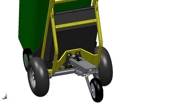
Novative Designs Inc. designs and manufactures a line of DC-powered, motorized, light material handling equipment. They recently made a new version of their hand truck that has an optional rear stabilizer arm. They call this addition a "stinger." It pivots about an axle to let the hand truck angle vary on hills, ramps or uneven ground.
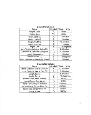
Novative had only planned on 1200 pounds of force, so the spring assisted shock is too undersized. For example, with an 800-pound load, the forces compressing the spring are calculated to be approximately 8400 pounds. They have not found a shock with a 6” center to center install distance that can handle that load. They need your help!
Your design needs to bolt up to the existing hand truck and provide ample strength, durability, and flexibility. Use an adjustable rate control device such as a spring assisted shock, gas spring or hydraulic shock, or even a simple rubber bushing. View the main image and drawing, below, and use the Download Specifications button to learn more about the existing design.

You must include:
- STEP or IGES file format
- 3D file from any CAD software you choose
- Description explaining your design idea and how it works
Judging criteria:
- How many of the existing parts can be salvaged, specifically the arm (part number 13027) and the left and right mounting brackets (part numbers 13026L and 13026R)
- Simple, durable and cost effective design
- Option to provide additional deployed stinger positions so user can adjust the preferred angle of the hand truck to suit his/her height and angle preference. For example a low, medium and high position, and then stowed position such as it is now.
The competition is open to everyone. Multiple entries are acceptable. Team entries are welcome - prize will be transferred to team leader. Participants may only win one prize per Challenge.
Tag your entry with “STABILIZERLEG” when uploading to GrabCAD. If you submit through the "Submit entry" button, this should be added automatically. Only entries with valid tag will participate. Only entries uploaded to GrabCAD through the "Submit entry" button on this Challenge page will be considered an entry. Private entries are not eligible.
By entering this competition, you 1. Warrant that the work is your original work. 2. To the best of your knowledge, it is not, and has not been in production or otherwise previously published or exhibited. 3. Neither the work nor its use infringes the intellectual property rights (whether a patent, utility model, functional design right, aesthetic design right, trade mark, copyright or any other intellectual property right) of any other person.
______________________
If you think an entry may infringe on existing copyrighted materials, please email challenges@grabcad.com.
Applicants are not entitled to any compensation or reimbursement for any costs. The applicant’s participation shall not constitute employment, assignment or offer of employment or assignment.
The sum of the Awards is the total gross amount of the reward. The awarded participant is solely liable for the payment of all taxes, duties and other similar measures if imposed on the reward pursuant to the legislation of the country of his/her residence, domicile, citizenship, workplace, or any other criterion of similar nature. Only 1 award per person.
Only public entries will be considered. Any private submissions will be made public at the Challenge deadline.
We will release the finalists before the final announcement to give the Community an opportunity to "vote" for their favorites in the comments. The jury will take these into consideration when picking the final winner. This new addition is based on feedback from you!
Winning designs will be chosen based on the rules and requirements. This Challenge ends on February 23, 2014 (11:59pm UTC). Winners will be announced by March 23, 2014.
(Update: Feb 21, 2014) EXTENDED deadline. The Challenge will now end February 28, 2014 (11:59pm UTC) and winners will be announced by March 28, 2014.
Void where prohibited.
$1,000 cash + GrabCAD scrapbook
$200 cash + GrabCAD scrapbook
$100 cash + GrabCAD scrapbook
GrabCAD scrapbook
The jury will be comprised of Novative Designs and GrabCAD experts.

Novative Designs Inc designs and manufactures a line of DC-powered motorized light material handling equipment under Haulzall brand.
 Sara Sigel
 Darryl Berlinger
Have an awesome idea for this competition? Want to win cool prizes? Sign-up now to upload your entries.

If you don't receive the email within an hour (and you've checked your Spam folder), email us as confirmation@grabcad.com

74 comments
Dorjano Barr over 11 years ago
One question though.... Do you really need a suspension type of "stinger"? Couldn't it be just a rigid one, with a softer - maybe inflatable tire? Because as I see It the shock absorber as it is ...well is no good.
Jonathan Brazeau over 11 years ago
along those lines, can this not be solved simply by using a stiffer spring, or having a stiffer spring custom made?
Darryl Berlinger over 11 years ago
Our prior hand trucks have fixed rear stabilizer arms. The problem with them is that when an operator goes down a ramp, the tendency is to lean the truck back into the hill, which then loads the rear wheel(s) and unloads the front wheels. We do not want that to happen since the font wheels provide braking, and they need positive traction (weight) to function well.
A stiffer spring is possible, but we are looking for an off-the-shelf shock if possible and have not found one that has the capacity and can fit in the 6" center distance
Dorjano Barr over 11 years ago
Thanks Darryl for clarification but I still don't get it quite well. How does a shock absorber help prevent that?! Anyways I'll submit my design(s) in few days.
Cheers, D.
Jonathan Brazeau over 11 years ago
but the only way to stiffen things up without touching the shock is to increase or decrease the leveraging using linkages etc. like in auto or bike suspension, but you still want to use the standard parts??
Pierre over 11 years ago
Is it possible to get the 3D file in .STEP
Hevi over 11 years ago
What is the exact dimmension of this spring? Can we replace it with another one? ;)
Darryl Berlinger over 11 years ago
Darryl Berlinger over 11 years ago
We should have an .stp file up shortly.
regarding the spring, the install dimensions are 6" center to center, and the OD of the spring is approximately 2".
Yes - Any spring, shock or rate control device can be used, but the preference is to use something that is off the shelf, and can fit in the existing center distance. If this is not possible, then we are happy to review a more creative approach.
Darryl Berlinger over 11 years ago
Forgot to address the heat treat question. We have discussed heat treating the spring, and it could be done, but then we are getting into a custom spring. The ideal solution is a "screen door -type " sping/shock by which the tension of the compression resistance can be adjusted by turning a screw or some other device. Crude analogy, but the best way to describe what we are after.
Hevi over 11 years ago
The for the spring is 8400 pounds of force? (it is the same as aprox. 4200N?)
Darryl Berlinger over 11 years ago
Our defined worst case scenario is an 800-pound load on the hand truck with the CG about 42" off the ground. With this load, we roughly calculated that the compression force acting on the shock is about 8,400 lbs, which If my conversation calculator is correct, is 37,365 N.
Hevi over 11 years ago
It's hard to believe that this spring gets almost 4 tons!!!! If it's right, when this spring breaks it should kill the man who is using this machine ;)
David Thornley over 11 years ago
Is it possible to get the source files in another format please, as I am unable to use EASM.
Tom Martin over 11 years ago
This is an interesting problem, what is the maximum desired displacement of the spring at 8400 lbs? or what is the desired spring rate?
Azrul Amir over 11 years ago
If the load is 800-pound, and the spring is at an angle, how can the compression force acting on the spring be 8400 lbs? The spring should be experiencing compression force of less than 800-pound.
Hevi over 11 years ago
Azrul is right, from 800punds = 365kg of weight you get aprox. 3650N of force in vertical direction... so... theres something wrong ;)
DÈmonic LÒrd over 11 years ago
yea thats right how can you get such a large force over 3.65kN with such a low weight of 365kg ?? with the 1200 pounds of force should be enough if you have dual or triple spring put next to each other.
Darryl Berlinger over 11 years ago
I will check our calculations and either verify or correct.
With the full weight on the truck, we expect the spring to compress approximately 3". Stp files should be up later this morning.
ZC Design over 11 years ago
Why not just use tooling springs? They're cheap and much smaller.
Hevi over 11 years ago
I did this in my private entry ;)
Tom Martin over 11 years ago
I think the 8400 lbs force is concevable because the 800lbs weigt at units CG which give a considerable amount of leverage.
Hafidz over 11 years ago
in assembly drawing the diameter caster wheel is 10" but in catalog product specification diameter caster is 8". which the true?
Sara Sigel over 11 years ago
A STEP version is now available via the download specifications button!
David Thornley over 11 years ago
Thanks Sara! It would be helpful to also have the frame from the motorised sack truck, as it useful to have the interface detail to fully understand where improvements can be made
Darryl Berlinger over 11 years ago
This comment was removed
Hevi over 11 years ago
Anderl, I think "yes", but I'm waiting for the full assembly - I think like we all :)
Hevi over 11 years ago
@Sara - how to change private entry to public? :/
Sara Sigel over 11 years ago
@Hevi email me sara@grabcad.com
Darryl Berlinger over 11 years ago
Anderl - You are correct - part number 13030 does not work as it is shown on the model, so yes - that part is not to be used and a new part will be used in its place. in order of expense, part number 13027 is the most expensive, so it would be preferable to use that one if possible. However, forgoing a much better complete design just because we want to salvage some parts is not prudent, so if a much better/cost effective design solution requires starting from scratch, so be it.
Hevi over 11 years ago
When we can have the full assembly model in STEP/IGES file?
Tasos Georgopoulos over 11 years ago
Mr Berlinger can you please verify the correctness of the maximum spring reaction force to be 8400 lbf (37365 N). This load is really big. There are structural problems arising if we take the max load requirement as granted.
Hevi over 11 years ago
Tasos - are u sure that there could be so huge force? ;) If there is accumulated so huge power I think this truck should jump into sky =]
David Thornley over 11 years ago
Hi Tasos,
Hevi is correct, your conversion is incorrect. 900lb to kg is 408kg therefore equivalent to approximately 4002N. In your calculation you have used the force of gravity twice.
David Thornley over 11 years ago
Hi Darryl,
In determining the best solution for the support leg, it would be beneficial to have a step model of the sack truck frame, with the center of gravity for the load identified in the model. Please include the package limitations for the operating arrangement and for transport. These elements are necessary to understand the function and operating conditions of the product.
Details of the motor arrangement are unnecessary.
Jonathan Brazeau over 11 years ago
800lbs with gravity as the only source of acceleration makes about 3567N of Force by my calculations.
Jonathan Brazeau over 11 years ago
the problem is the angle of your shock in relation to the "swing arm" is too low, the angle needs to be increase, it will increase the force the spring will withstand.
Jonathan Brazeau over 11 years ago
Just curious, how is the arm lifted up into the upright position? it looks as though there is a quick latch system that clips into the shock? I'm assuming this is unlatched and the shock raises up in the slots while it's raised upright.....
Jonathan Brazeau over 11 years ago
Furthermore,
What are the stinger and brackets made out of? Would welding or simple modifications to these parts such as cutting onto these parts be an option???
Tasos Georgopoulos over 11 years ago
Guys just read the description again: "Novative had only planned on 1200 pounds of force, so the spring assisted shock is too undersized. For example, with an 800-pound load, the forces compressing the spring are calculated to be approximately 8400 pounds. They have not found a shock with a 6” center to center install distance that can handle that load. They need your help!"
---> So just do the conversion 1lbf (pound-force) = 4.448N. That means 8400 lbf of the spring reaction force is approximately 37365 N (just use whatever unit conversion tool you like is the same).
That is why I want someone from Novative to verify that the amount of the spring reaction force is correct, or just give us the whole assembly structure in order to re-calculate the whole thing from scratch.
Tasos Georgopoulos over 11 years ago
Do not base your calculations on the 800 pound load but on the spring reaction forces --> 8400 pounds. That's the amount of force that the stabilizer must overcome in order to be functional.
Jonathan Brazeau over 11 years ago
@Andi. Thanks, but I'm wondering if we can add welds onto it etc. Keep it but modify it sort of thing. There's some confusion with the force calculations. I'm a smart dude but it's definately been a while since I've taken physics and I'm sorta confused which formula's, calculations to use. I need some concrete figures, perhaps from a suspension specialist. In anycase, I have a few common sense ideas that I think would improve things, just not sure about the math.
Jonathan Brazeau over 11 years ago
Andi, yep, I was thinking the exact same thing but like you said, to get it be able to also be put in the upright position would be tough without adding in a bunch of parts.
Hevi over 11 years ago
So what about this full or dumbed down assembly? I did some reaserch and calc for force in this and I would like to continue my design :)
keith over 11 years ago
Can you post up the maths, i.e., I don't see the 8400 lbs e.g assume cart at 45° and resolve forces, Tan(45)*800lbs = 800 lbs, then 800 lbs/Cos(45) = 1131,37 lbs Your current spring goes solid at 43mm and this is at 911 lbs, So 1131,37 lbs (without resolving further) is not so far away?
Hevi over 11 years ago
@keith - for me u r right; force calculation is wrong for sure - I have my own calc., I will post full scan of it later...
Sara Sigel over 11 years ago
The 'Download specifications' button now has new information for calculating the force. Check it out!
Hevi over 11 years ago
I have uploaded my own calc. - GAS SPRING v1 and I'm confused...
Hevi over 11 years ago
So, you have 7697lbf = 34237.7N.... it's about 3.5 tons of weight? Right? Let's say screw no. (16) on your drawing is made from 1.4541 material... after doing some calc for screw cutting - conclusion - this screw should have almost 24mm in diameter, almost 1inch... and it has 13mm right now... that is the first thing... second one - how much material is there in the corner of main part (1) near to the (16), there where the screw is mounted? One moment... 6mm... hmmmmmmmmmmmmmmmmm.... 3.5 tons of weight (7716lb) and 6mm of material... eeeeee... no chance that it is gonna work :)
Hevi over 11 years ago
Last thing - I asked for help with these calculations my old academic teacher - 75yrs old man, 40yrs experainace in mechanics at university... I believe him :)
Hevi over 11 years ago
4th - 14th Prize should be a scrapbook ;)
Jonathan Brazeau over 11 years ago
a scrap book to do more calculations with......)
Hevi over 11 years ago
hah! true :D
Sara Sigel over 11 years ago
We added a skeletal STEP file of the hand truck frame so you all can work with a full model. We hope it will be helpful for you!
Hevi over 11 years ago
Hmmm... 2 days left, I almost finished my solution as a long description in PDF file :/ ...hmmmm
greg j waerhouse over 11 years ago
Great idea the skeletal! But unfortunately, a little bit late for me. I had to rely on a scaled image to check clearances on my design. But anyway...thanks!
Sara Sigel over 11 years ago
We've extended the deadline to now end February 28th so you can include the new model to help you with your design. We apologize in the delay getting it to you!
greg j waerhouse over 11 years ago
Out of curiosity, 6” center to center install distance, is it with the shock fully compress (Or at least at the operating position) or is it the "free" center to center distance?
Pablo over 11 years ago
How much is the length (center to center) of the spring totally compressed?
Darryl Berlinger over 11 years ago
When fully compressed, the shock is approximately 3 to 3.5" center to center. Note that is the shock (not the spring). The spring itself never is fully compressed. The internal guide is what bottoms out before the spring is completely compressed.
Jonathan Brazeau over 11 years ago
congrads to finalists! All great choices, I called most of them )....give me some time to list my favs.
Quintin Bannink over 11 years ago
It's great to hear that Novative is actually going to manufacture some of the designs to test them out! - It would be great if they could post some images. I must say - I would have liked to see Jonathan's design as one of the finalists, I think his design and comments sparked allot of thought for the rest of us.
Jonathan Brazeau over 11 years ago
Lol, hey Quintin, thanks man but I really think the way to go with this one is with a linkage system, not sure why my design got so much attention from people, I hated it, it was awkward and ugly, but GC can still put me in finalists if they want )))) hehehe. If I would have had time I would have dabbled with a linkage system for sure. Yours is great, I really like Carlos's design also. Good challenge, just a lot of math and not enough time for this one.
Quintin Bannink over 11 years ago
Darryl & Sara - Please go check the comment I left on my "Stinger Fix" - I don't think you understood the force reduction "Ratio".
Sara Sigel over 11 years ago
As you may have noticed, finalists are announced! http://grabcad.com/challenges/stabilizer-leg-suspension-challenge/results
.
Thanks to everyone who participated in this tough Challenge - and you're right @Quintin a special thank you should go out to participants like @Jonathan who went out of their way to give other entrants advice. Novative Designs will be performing tests (we'll try to get pics!) and looking in-depth at each requirement category up until our announcement of the winners.
.
If the jury had questions about your design feel free to add comments, expand your model description, or add a rendering to help explain. To all the other participants and followers: Which one is your favorite? Did we leave anything amazing off the list? Let us know in the comments!
Chuma A over 11 years ago
Really interesting challenge! I couldn't understand the physics so I stayed away, lol. That said, I really loved Michael Feeney's MEF StabilizerLEG V3. Kudos to the winners!
Quintin Bannink over 11 years ago
Any news on the results from the testing?
Sara Sigel over 11 years ago
Winners are announced! Congratulations to the Top 10 designs!
http://grabcad.com/challenges/stabilizer-leg-suspension-challenge/results
.
Thanks to everyone who participated in this tough Challenge! Novative Designs looked in-depth at each requirement category and produced parts for the two top designs. Check the models for pictures of the produced parts! They are likely to produce and test a few more designs, as well. Stay tuned here for updates in the future. They were impressed with all of your designs and are excited to move the process forward! You can expect their final product to combine the best all of the winning entries.
Hevi over 11 years ago
For me... this was one of the coolest design contest. Thank you Sara and Darryl, thanks to Novative Designs and GrabCAD team.
Jonathan Brazeau over 11 years ago
Congrats Hevi! Definitely an awesome competition and good show! Congrats to all finalists also.
Hevi over 11 years ago
One more time thanks and congratulations to everyone :)
Max_Marios over 11 years ago
Congratulations to all the participants!!! Many thanks to Novative for setting up such a great contest!!! Hope to see you soon in other challenges...
A0I0A over 11 years ago
Nice challenge. Congrats to all the participants and winners. Had high hopes for this challenge, but stuffs happen.
MUSTAFA TOUIL over 11 years ago
congratulation to all winners.... :)
Please log in to add comments.
Log in