Hi GrabCad,
I´am working on a privat project, and since a few days im having some problems.
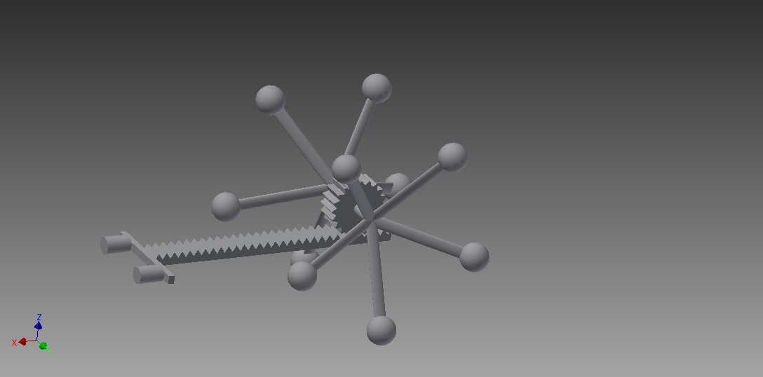
Picture1
I´m trying to design a mechanism for this problem.
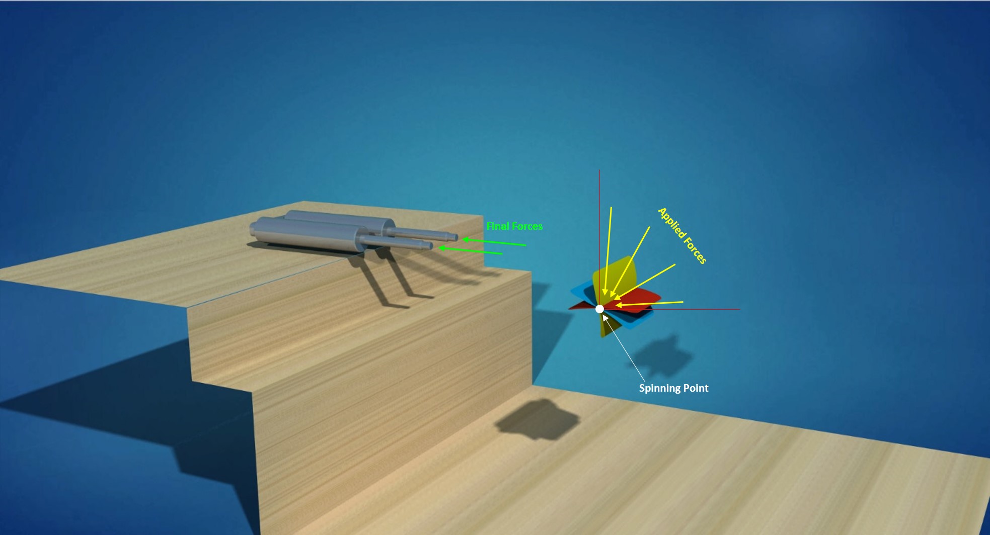
Problem: I have some input forces (Yellow arrows) and im trying to transform them into the output forces(green arrows) to push the gas springs damper inside. The yellow forces should be applied from an angle of 0° to 90°, the outcome however, should be the same = green forces.
The mechanism should fit inside this envelope. (see picture 2)
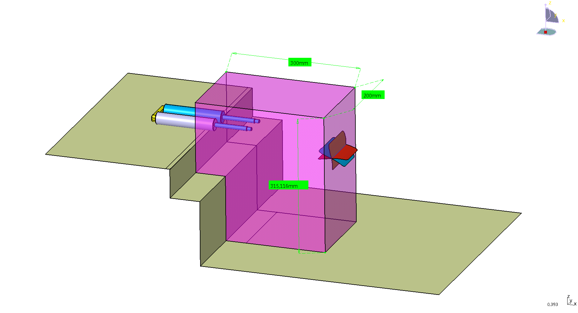
Picture2
I´ve tried many methods and designs but I had no success so far.
Does anyone of you have any idea on how i could design the mechanism?
Thank you in advance!
Assuming the yellow forces produce a clean rotating motion, you can use a pinion and a gear rack to turn rotation into linear motion.
In which case the gear rack will of course have to slide on something.
if you mean the rotation axis by the spinning point, and if those yellow forces are all targeted to this axis as seen in picture, i don't see that figure can move at all.
The rotation axis can be somewhere else, it doesn´t have to be exactly like in the picture. The main goal is to transform the input forces from a 0° to 90° angle to the output forces.
I like this idea.
So you´re saying that the yellow forces should create a clean rotating motion no matter if the force is applied from a 0° or 90° angle?
If it is possible yes.
I don't know the origin of the forces so it was just an idea.
But from what you have written it seems like the simplest option.
Thank you Relnaldo!
This solved half of my problem.

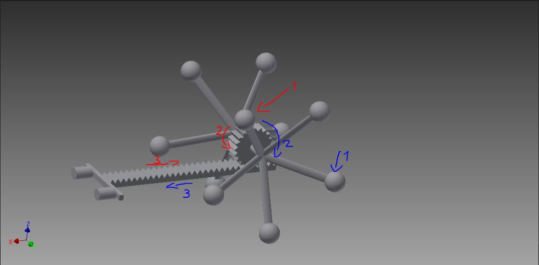
The only issue now is the following. When blue force 1 is applied, the outcome is blue force 3. This is what i need.
But when the red force 1 is applied the outcome is red force 3, and this is in the opposite direction as what i need.
Maybe the kind of mechanism i need is not even posible?
On your initial picture input force vectors are all pointing to axis, so they are not producing a torque.
It looks that you want to apply straight movement in several possible directions.
If the only problem with the rack and pinion set up is reversing, then do not connect the lever system directly to the pinion gear, but rather connect it to a main shaft that drives the pinion clockwise by way of a one-way clutch. Then put a bevel gear on the pinion and couple that bevel gear with two other bevel gears so that the axis of the third bevel gear is coaxial with the main shaft and driven by the main shaft by a second one-way clutch when the main shaft rotates counterclockwise. This will then drive the pinion clockwise once again. In short, the pinion goes clockwise regardless of the rotational direction of the input.
Sebastian, try a rotating two-arm lever mechanism, the rotary axis is close to the lower plane, one branch takes power, the other carries power.
At last we have found an engineer who did not fall asleep in their basic mechanics class with an understanding of basic force vectors
Yes, you´re right, the picture is a bit confusing. espacially that "spinning point". How you said, my goal is to apply straight movement on the yellow,blue,red surfaces.
It sounds to me like you need some sort of fluid power system: Imagine you had a hollow container filled with fluid on the inside and imagine that container had pistons oriented in the direction of your yellow forces, whenever the yellow forces pushed a piston down it would generate pressure inside the container which could then be directed toward the green forces.
this is basically a hydraulic pump & cylinder design.
I think about flexible hydraulic cylinder (like a rubber ball toy) that can be squeezed at any direction, and a duct, passing pressure from the ball to linear hydraulic actuator.
There are a multitude of ways to convert rotary motion to linear. Here are two:
Crankshaft / connecting rod arrangement:

Hypocycloidal linear drive.
A short video:
A few questions:
Exactly what spins the impeller?
If you don't receive the email within an hour (and you've checked your Spam folder), email us as confirmation@grabcad.com