Learn about the GrabCAD Platform
Get to know GrabCAD as an open software platform for Additive Manufacturing
Visit our new homepage


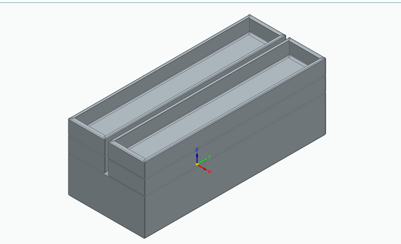
Could someone please provide me with resources to complete my cantilever toolbox CAD assignment? I need to create a CAD design similar to this example: [https://www.sealey.co.uk/product/5637183402/530mm-4-tray-cantilever-toolbox]. I’m new to CAD and don’t know where to begin, so any guidance would be greatly appreciated. My plan is to create one large box and four smaller boxes (copy past 3 times or mirror), then assemble them together. I’ve already completed one large box and one small box, but I’m finding the next step quite confusing. (For this we are using solidedge in school).


Would this help:
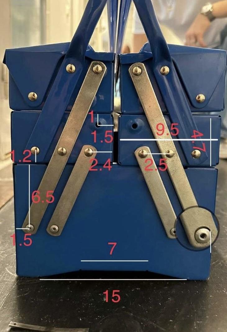
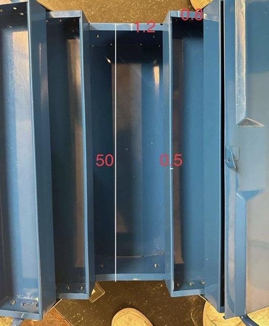
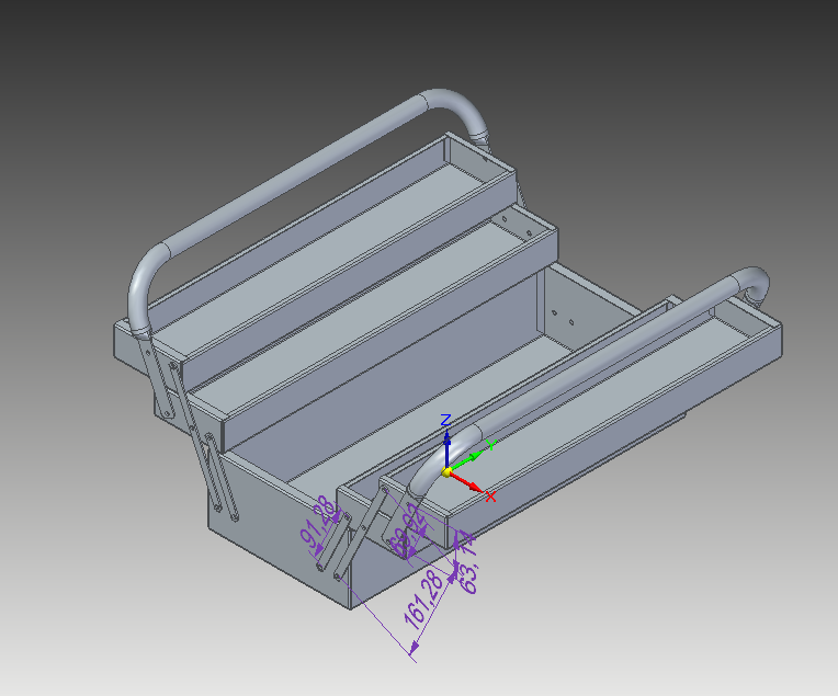
I have made it this far:

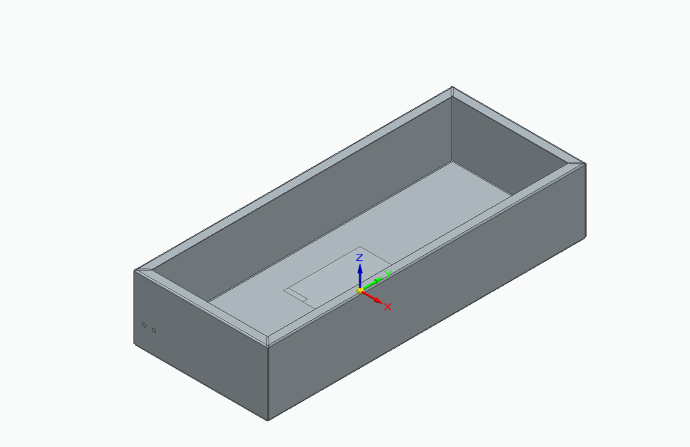

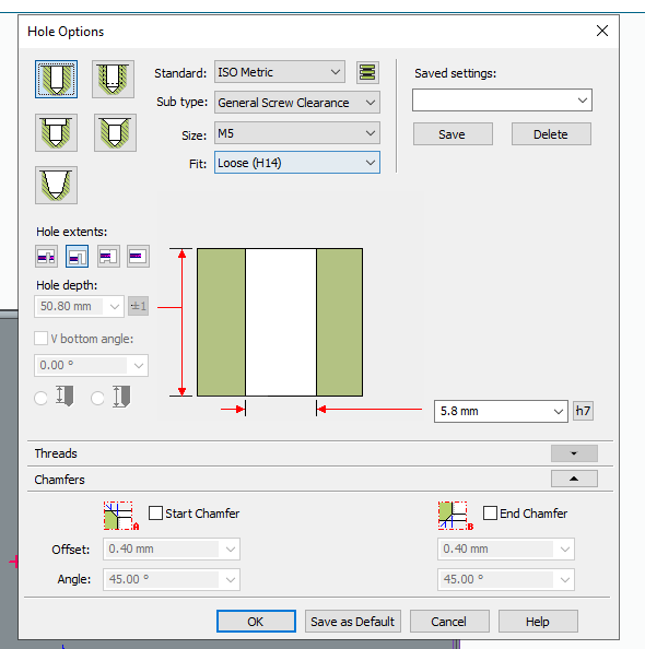
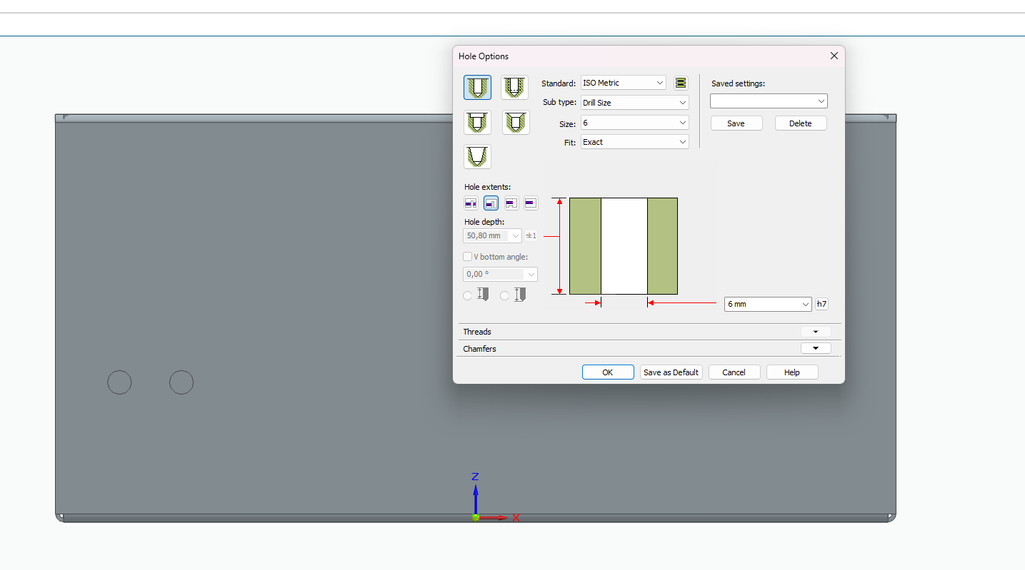
I have problems with the holes. Dont know the places i should make a hole and which hole options i should use:
Should i assemble the boxes first and then make the holes?
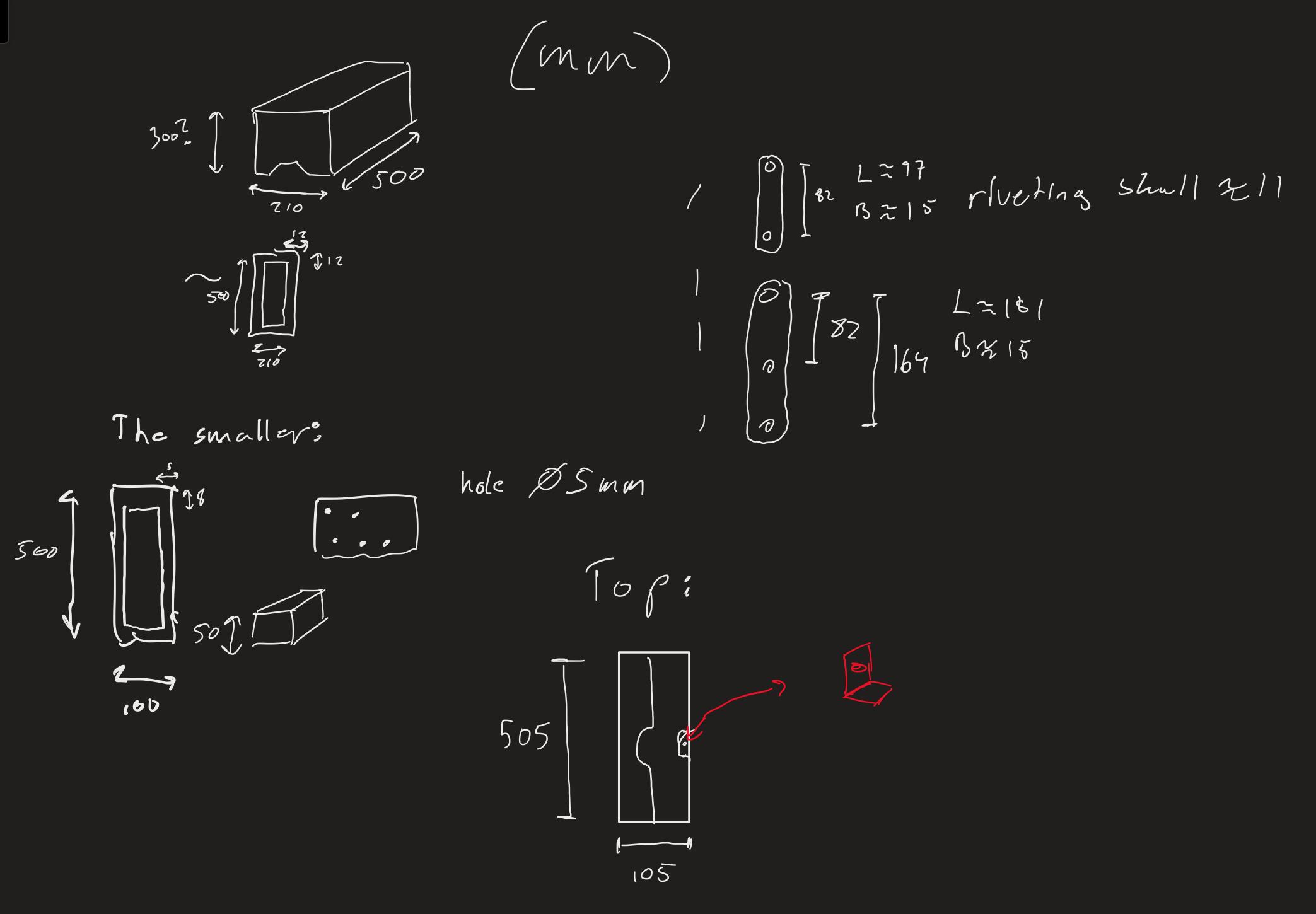
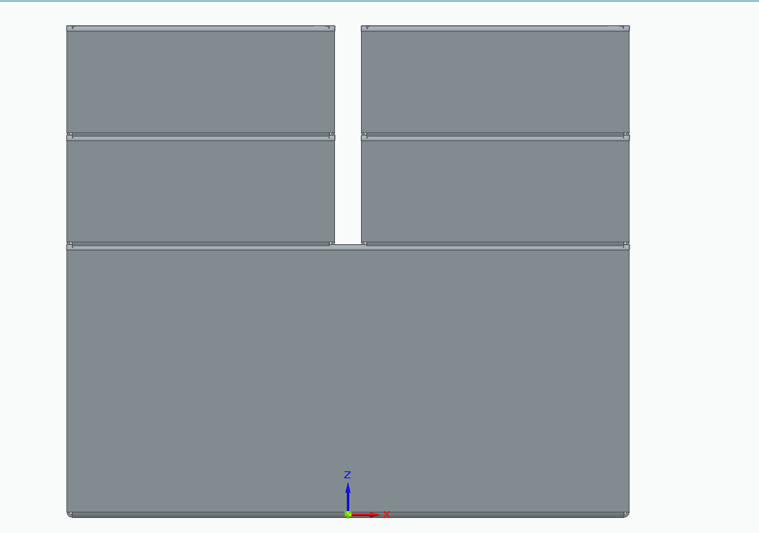
First, this is my toolbox, so I assumed boxes 300x150 and 150x100 mm.
“ This is only a displaying method. Do not stick on dimensions. . You may arrange them according to your design later.”

2. Defining block
We changed the upper box into a block to make our studies easy and also we will apply 3 connection points in block editor mode. I assumed 50mm is enough between for each connection point at middle level height.
I defined 3 connection point as shown in drawing

“ İf you don't know how to create a block, I explain,
First choose lines, arc circles etc. and CTRL-x Cut, then CTRL Shift Paste as a block.
This is the most easiest way to create a block on AutoCAD”

Our drawing is has become more convenient with the upper box block.
3. Defining box positions in open and closed state
I assumed that the upper box , while located upper box at 125 mm away from the closed state, it s providing enough gap to take something from the box or put something in it.

4 . Define link lengths and pivot points.
We will open our upper box block in block editor again. Trial and error method may use to define appropriate linkage lenghts or simple assume 150 mm half length of our box height w emay choose to see what we will have..

When block editor closed our drawing give us a connection points.

To find a pivot point, only draw a line from the center of the yellow circle to the intersections and to define the second point, we may apply the same method from the center of the first green circle and intersections of green circles.

5 . Optimisation
As shown in last drawing, the bottom box pivot point is too high and length linkage length are too short. We need to extend them to make a mechanism, turn in more easy operable state.

Radius extended 50 mm to obtain 150mm in block editor mode.

After turning in back to drawing mode, now we get two more different pivot point positions.
What we are doing here is trying to optimise relation between pivot points and linkage length.
You can find a sample in the Wikipedia link below to understand how much variation may be drawn in this mechanism.
https://en.wikipedia.org/wiki/Four-bar_linkage#/media/File:4bar_curves.gif

As shown in drawing, red lines are too short according to the green lines and neglecting thus First stage linkage length obtaining from Green line length.
6. Defining the upper box connection point and second stage linkage length.
We will define another block at the same dimensions as the first box, but connection points will not be the same because the second box has got a longer radius, thus following a different trajectory while opening and closing.

according to drawing second stage linkage obtained 110 mm lenght.
7. Drawing linkage bar
Now we have enough data to draw linkage bars as shown

150mm hinge is obtained from first stage
110 mm hinge is obtained from second stage
260mm hinge is obtained from multiplying first and second stage
Ps. hinges designed as sheet metal.
8. Accomplish Assy with applying linkage bars in to drawing.

To refine drawing, seperate open and closed states

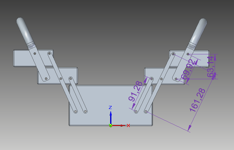
As you see our tool box trays are working betwween Open and closing postion
İf you got how to apply this method into simple four linkage bar mechanism, it means
Now you can also design this;
 . (metro train door mechanism)
Or you you can design this;

. (Bus luggage door)
Or you can design this

all of them are working on same four linkage mechanism rules.
lets talk about First question those M5 bolts. You need Mushroom head square neck bolt.

This kind of bolts usually using on sheet metal and wood constructions. As its name this is self lock bolt so no need to screwdriver or wrench to tighteen. Please note that , bolt end is square shape so you must be open square cut on your sheet metal according to bolt end size and on other sheet metal part must have hole according to standart M5 bolt..
here I am leaving link so you may have a look bolt's standart details
https://www.fasteners.eu/standards/DIN/603/
also You can downlaod 3d model from trace parts and link is here;
https://www.traceparts.com/tr/product/mushroom-head-square-neck-bolt?Product=10-11062001-216999
you will need a standart M5 bolt and washer to accomplish bolting assy. I am leaving other links here also;
I reccomend torque type Nut it doesnt loosen in time,

DIN 985 Bolt Prevailing torque type Nut; you can download from here;
https://www.traceparts.com/tr/product/d%C4%B1n-hexagon-nut-d%C4%B1n-985-m5-x-08-10?CatalogPath=TRACEPARTS%3ATP01001007009&Product=10-11062001-133256&PartNumber=DIN%20985%20-%20d%20M5%20x%20p%200.8%20-%2010
or alternatively you may use standart nut but you must apply anti loose washer.
DIN 934 Standart Nut, you can download from here;
https://www.traceparts.com/tr/product/d%C4%B1n-hexagon-nut-d%C4%B1n-934-m510?CatalogPath=TRACEPARTS%3ATP01001007009&Product=10-11062001-160766&PartNumber=DIN%20934%20-%20d%20M5%20-%2010
self locked washer for DIN 934 Standart Nut, you can download from here;
https://www.traceparts.com/tr/product/hobson-nordlockr-standard-washer-m5?CatalogPath=TRACEPARTS%3ATP01001017004003&Product=10-01072020-064277&PartNumber=WNHTDDM05

 2 questions: