

Design of impeller for centrifugal Pump


Here is a tutorial of "How to create impeller for centrifugal pump using solidworks. For video tutorial kindly check the link https://www.youtube.com/watch?v=TUxKqjk4vA0
-
Step 1: Understanding 2D drawing
First of all we will try to understand the 2D drawing for impeller for centrifugal pump.
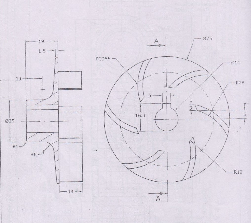
In above drawing, 2 views are given out of which left side view looks simpler as compared to front view.
-
Step 2: Sketching the left view on plane
Select right plane and sketch on it

Then draw half sketch on same plane as we will be using revolve command

-
Step 3: Revolving the sketch
Go to features, select revolve

After revolve, the model will look like this

-
Step 4: Creation of hole for shaft
Select front face and sketch on it.

Create a sketch using circle and lines.

Go to extrude cut

Select through all

Finally it will look like this

-
Step 5: Creating blade
Select front face again and sketch on it

Draw the sketch as shown in figure

Now go to extrude, select depth as 14mm

and click ok

-
Step 6: Create 6 blades
to create other blades, we will use circular pattern

Select face as reference, and feature as extrude. Enter no. of count as 6 and then click ok.

It will look like this

-
Step 7: Final rendering


-
Step 8: Video Tutorial