

Gearbox Sloshing effect


Flow of fluid inside a gearbox due to motion of gear.
-
Step 1: Simulation Setup
For this challenge we are running 4 cases of gearbox with two different clearances and with the two different fluids and observe the flow pattern of the fluid inside the gearbox.
3D Model :-
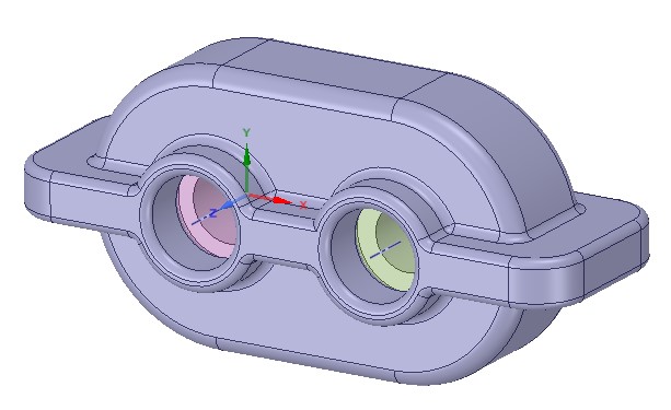
For finding the result using this 3D model is increase the computational cost and time to run the simulation and also we are having Academic license so some limitations for mesh generation. So we are extracting 2D model from 3D model and done simulation on it.
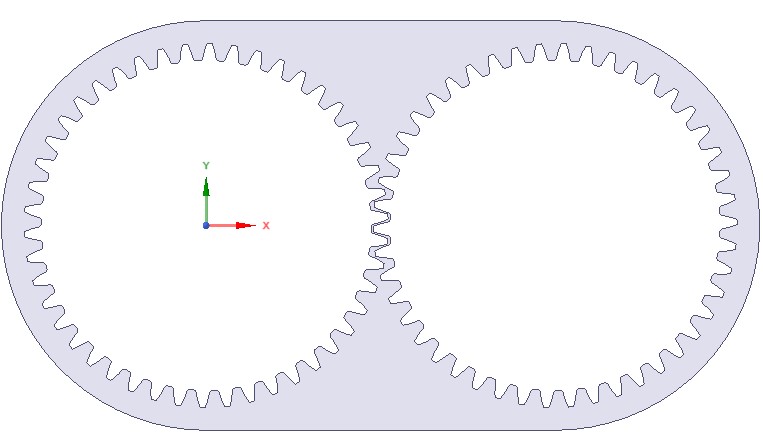
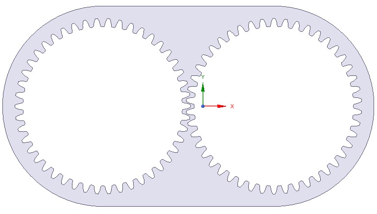
For performing this simulation we have two types of model
Model 1 : Low clearance
Model 2 : High clearance
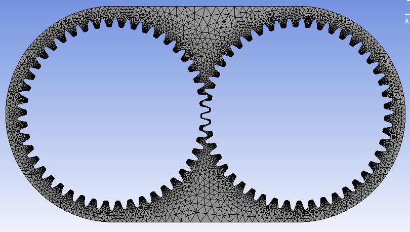
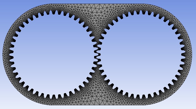
Meshing :-
For refining the mesh for this case we are using all triangle method
- Element size = 30 mm
- Capture proximity ON
- Proximity minimum size = 0.3 mm
- Number of cells across gap = 1
Low clearance
High clearance
So, now we have two fluid for running the simulation. Properties of fluid defined below.
1) Water
- Density = 998.2 kg/m^3
- Viscosity = 0.001003 kg/ms
2) User defined (Oil)
- Density = 871 kg/m^3
- Viscosity = 0.04006889 kg/ms
UDF - User Defined Function
For giving the motion to both the gear we have user defined function. Clock-wise motion provided to right gear and Anti-lock-wise motion provided to left gear.
#include "udf.h"
DEFINE_CG_MOTION(right_motion, dt, vel, omega, time, dtime)
{
vel[0] = 0.0;
vel[1] = 0.0;
vel[2] = 0.0;
omega[0] = 0.0;
omega[1] = 0.0;
omega[2] = 2.0e2; /* [rad/s]*/
}
DEFINE_CG_MOTION(left_motion, dt, vel, omega, time, dtime)
{
vel[0] = 0.0;
vel[1] = 0.0;
vel[2] = 0.0;
omega[0] = 0.0;
omega[1] = 0.0;
omega[2] = -2.0e2; /* [rad/s]*/
}
Simulation Setup :
First of all we added the UDF to the ANSYS so we can provide motion to the gear.
Setting up the physics for Gearbox sloshing in ANSYS fluent.
- For this case we are using pressure-based transient solver
- Velocity formulation - Absolute
- Gravity Acceleration
- X-direction = 0 m/s^2
- Y- direction = -9.81 m/s^2
For this case make sure dynamic mesh is ON
- Method for dynamic mesh = Smoothing, Layering, Remeshing
- Remeshing methods = local mesh
- Minimum length scale = 0.0001
- Maximum length scale = 0.002
- Maximum cell skewness = 0.7
- Size remeshing interval = 5
- Dynamic mesh zones
- right gear - right motion
- left gear - left motion
Center of Gravity Location
For Low clearance
- Left Gear
- X-direction = 0 m
- Y- direction = 0 m
- Right Gear
- X-direction = 0.115 m
- Y- direction = 0 m
For High clearance
- Left Gear
- X-direction = -0.0684485 m
- Y- direction = 0 m
- Right Gear
- X-direction = 0.0485515 m
- Y- direction = 0 m
For creating the fluid region inside the gear box we have option inside the adapt and refine and select for region inside cell registers.
For Low clearance
- Option - Inside
- Type - Quad
- Diagonal end point = (0.17112 -0.0375 0)
- Diagonal start point = (-0.05612 -0.0675 0)
For High clearance
- Option - Inside
- Type - Quad
- Diagonal end point = (0.11193 -0.03 0)
- Diagonal start point = (-0.13182 -0.0675 0)
Multiphase model setup
- Model - Volume of fluid
- Volume fraction parameters - Implicit
- Volume fraction cutoff = 1e-06
- Interface modeling type - Sharp
For solution we use patch command in initialization
- Phase - Water/Oil
- Variable - Volume fraction
- Value 1 for Water/Oil surface
Run calculation : Same for all the cases
- Time stepping method = Fixed
- Time step size = 0.0001 s
- Number of time steps = 2000
- Maximum iteration/time steps = 20
-
Step 2: Result
Case 1 : Gearbox with Low clearance and Water as a fluid
Fig : Residuals plots
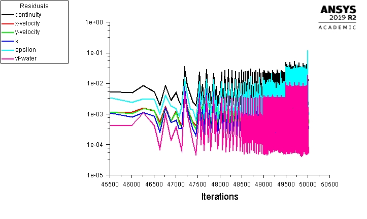
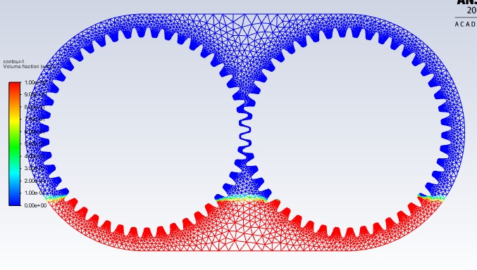
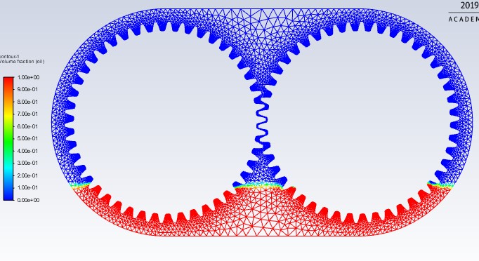
Fig : Volume fraction of Fluid at initial state.
Animation : Flow of lubricant fluid inside gearbox
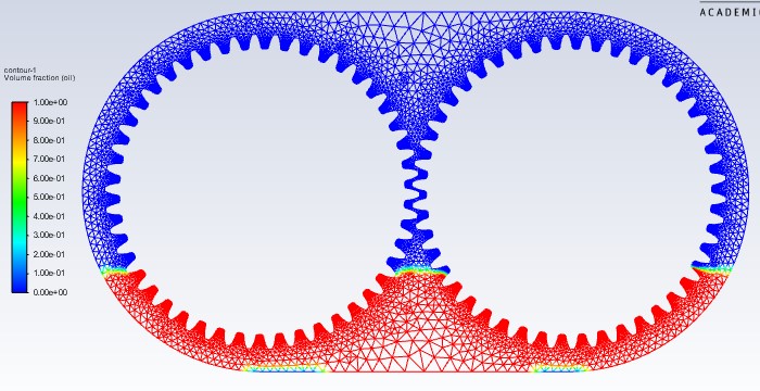
Case 2 : Gearbox with Low clearance and Oil as a fluid
Fig : Residuals plots
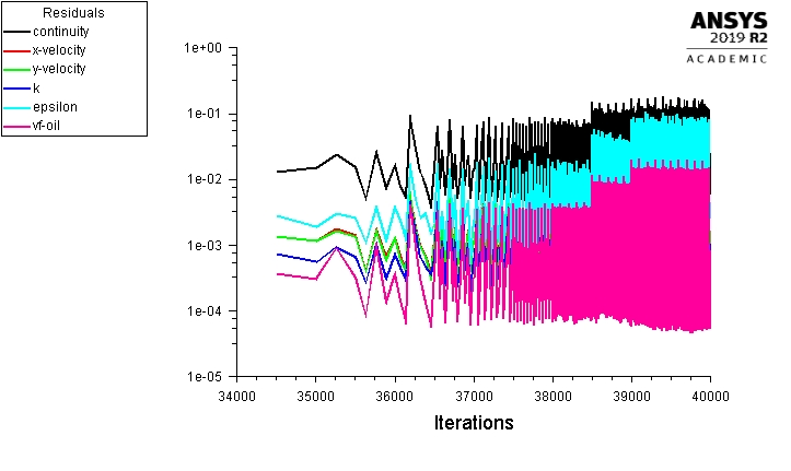
Fig : Volume fraction of Fluid at initial state.
Animation : Flow of lubricant fluid inside gearbox
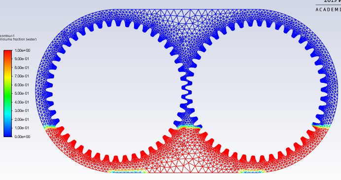
Case 3 : Gearbox with High clearance and Water as a fluid
Fig : Residuals plots
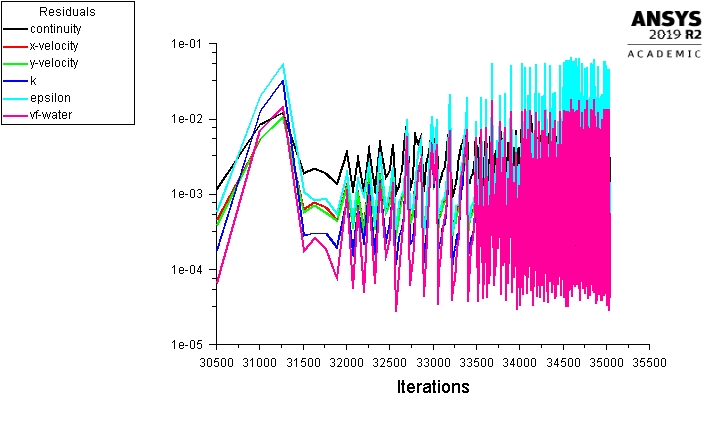
Fig : Volume fraction of Fluid at initial state.
Animation : Flow of lubricant fluid inside gearbox
Case 4 : Gearbox with High clearance and Oil as a fluid
Fig : Residuals plots
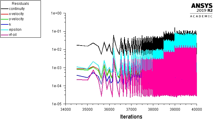
Fig : Volume fraction of Fluid at initial state.
Animation : Flow of lubricant fluid inside gearbox
Conclusion : -
- As shown by above Animation, we can see that both oil and water can work as a proper lubricant.
- All the teeth of the gears are covered in the lubricant after they completed 1 revolution.
- The difference between oil and water as a lubricant is that there is little sloshing with oil on the top of the gear teeth than water due to its higher viscosity and higher resistance.
- Oil has lower density then water means oil has lower mass per volume so it stick on teeth of gear for more time.
- The splashing in the top half of the gearbox is lesser for the high clearance model because there is much space between the gear to pass the lubricant through.