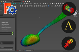
Mechanical stress simulation (FreeCAD 0.19 • FEM Workbench )

This tutorial give an overview of FEM Workbench on FreeCAD 0.19 which allows mechanical analysis by the finite element method. We will look at the steps to follow to applies a force of given value [N] to selected target geometry. Then perform a finite element analysis without going into details of the calculations.
-
Step 1: Open a model or create a new part
First, we need a part on which to do our analysis. I'm going to use a part that I have modeled before (the spoon you see below) but you can also use one of your own parts.

If you want to model same part I advise you to go see the tutorial Product Design #022 from Tutorial Field on Youtube, it's a good exercise to discover Draft Workbench (WB).
If you don't have a piece on hand and you want to move on quickly, create a rectangular paver shape with the Part WB :
1.1. Create new document,

1.2. Go to Part Workbench,

1.3. Create a box,

1.4. Give it height (70 mm for example).

You can now use your beam for the rest of the tutorial, I will continue with my spoon.
-
Step 2: Assign a material to the part
2.1. Go to FEM WB,


2.2. Creates a new container for a mechanical analysis,


2.3. Click on 'Material for solid' function,


2.4. Select a material from the database, ex : 'Steel-15CrNi6',

2.5. On the bottom select 'Solid',

2.6. Add your part by clicking first on 'Add' then on your part,

2.7. Click on 'OK'.

-
Step 3: Fix the part
3.1. Define a fixed constraint,


3.2. Select a point, edge or face at the extremity of your part,

3.3. Click on 'Add'.


-
Step 4: Apply a force
4.1. Define a force constraint,

4.2. Set a value in [N] to be applied uniformly, ex : 1000,

4.3. Select a face,

4.4. Press 'Add',

4.5. Press 'Reverse direction' to apply force in right direction,

4.6. Press 'OK'.

-
Step 5: Make a mesh
5.1. Select 'Body' of your part,

5.2. Create a mesh from your part with Gmsh,

5.3. Let the automatic setting of the elements and press 'Apply'...

... or set them with value of 'Max' and 'Min' elements sizes,


5.4. Press 'OK,

-
Step 6: Setting analysis parameters
6.1. Double-click on 'SolverCcxTools',


6.2. Write .inp file,

6.3. Run CalculiX...
6.3.1. You will have the message "Calculix done without error",

6.3.2. if you have an error as below it will not work, try to change the size of your elements or try to re-start procedure using a STEP format (it worked for me).

-
Step 7: Show results
7.1. Double-click on 'CCX_Results',

7.2. See results as Displacement Magnitude...

Displacement X...

Displacement Y...

Displacement Z,

7.3. You can also have a view of part deformation.


