Learn about the GrabCAD Platform
Get to know GrabCAD as an open software platform for Additive Manufacturing
Visit our new homepage
Home
Control
Shop
Streamline Pro
Partner Program
Print
Community
Log in
Library
Challenges
Groups
Questions
Tutorials
Engineers
Blog
Log in
Learn from thousands of free Tutorials.
New user?
Join the community
or
log in.
Tutorials
Most liked all time
Recent
Most liked
Most viewed
Most commented
This week
This month
All time
Category
Design & CAD
Modeling
Drafting
Assemblies
BOM
Dimensioning / Tolerancing
Translations
Manufacturing & CAM
3D Printing
Tooling
NC Machining
Composites
Measurement / Inspection
Simulation & CAE
FEM
CFD
Kinematics
Process Simulation
Engineering Fundamentals
Theory
Process
Standards
Other
Software
Snagit
Alibre Design
ArchiCAD
AutoCAD
AutoCAD Electrical
Autodesk 3ds Max
Autodesk Alias
Autodesk Inventor
Autodesk Maya
Autodesk Revit
Autodesk 123D
BricsCAD
Bentley MicroStation
BlenderCAD
BobCAD-CAM
CATIA
Delmia
DraftSight
FreeCAD
Femap
Fusion 360
Geomagic Design
IronCAD
JT
Kompas-3D
KeyCreator
KeyShot
Lagoa
Luxology
Mastercam
Moi3D
NX Unigraphics
OBJ
Onshape
OpenSCAD
Parasolid
Powermill
Powershape
Pro/Engineer Wildfire
PTC Creo Parametric
PTC Creo Elements
Rhino
SpaceClaim
SOLIDWORKS
solidThinking Evolve
Solid Edge
SolidFace
STEP / IGES
SketchUp
STL
TopSolid
TinkerCAD
T-Flex CAD
TurboCAD
VectorWorks
ViaCAD 3D
VRML / WRL
ZW3D
GrabCAD Print
Rendering
GrabCAD Community
GrabCAD Workbench
Text file
3D Manufacturing Format
Cinema 4D
Other
Skill level
All levels
Beginner
Intermediate
Expert
Tooling
×
Process
×
Standards
×
I Built a Military Robot
Engineering Juice
in
Process
46
6
Intermediate
Mobile, military robot optimized for use in desert environments which can be controlled remotely or autonomously and can collect/ stream video to a VR headset via its front mounted camera. The method of movement is a continuous track, created using steel roller chain connected by fasteners with 3D printed links. These loops sit on a custom designed drive sprocket and idler sprocket with 4 shock absorber loaded roller pins that act as the suspension system. The drive motors are powered by '18650' batteries, directed by a raspberry pi 4 and connected to a motor controller. For connectivity, a mobile device can connect to the pi's external antenna as it is a WiFi access point. From here, directions can be sent to the robot from the mobile device using the Node Red GUI and additionally, the entirety of the main raspberry pi computer can be accessed for the use of sending custom commands for autonomous movement.
Fusion 360
printed
3d
rc
programming
pi
raspberry
electronics
360
fusion
robot
robotics
DIN 580
Ivo Jardim
in
Standards
33
1
Expert
Suspension Bolt
bolt
580
din
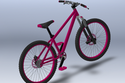
How to Prepare Your 3D Model for Manufacture
Russell Everard
in
Process
32
1
Expert
Using this ladies bike model found in the thousands of models available on GrabCAD I have made a step-by-step guide on how to break down your top level assembly for the workshop or for outsourcing.
SOLIDWORKS
cutting
laser
fabrication
cnc
fixings
assemblies
manufacture
solidworks
How to 3D Print Jigs & Fixtures, Part 3: Advanced Features and Advanced Materials
Shuvom Ghose
in
Tooling
17
4
Expert
Building on parts 1 and 2 of the series, this tutorial takes you through an ENTIRE agile design cycle for a real fixture we needed in our office, exploring the use of DFAM, advanced infill techniques to save printing time and finishing by going through a material selection process to print in one of the stiffest materials out there- Nylon 12 Carbon Fiber! It's a total, soup-to-nuts, fixtures tutorial!
fiber
dfam
stratasys
fdm
advanced
carbon
fixture
How to Create a Mold Using SolidWorks
Sérgio CAD CAM
in
Tooling
17
0
Beginner
How to Create a very, very simple Mold Using SolidWorks, step by step.
3d
cad
solidworks
injecao
injection
molde
mould
mold
How to design Complete Robot using Voice Assistant like JARVIS in Fusion 360
Rugved Chavan
in
Process
17
1
Intermediate
4-wheeled Robot Design Frame is 3D printable. Components - 1. Raspberry pi 4 2. Sony WebCam 3. Normal 3.5 mm jack Speaker 4. Custom Frame 5. MI 20000 mAh powerbank 6. 100 RPM Dual Shaft BO Motor - Straight with wheels Custom Voice Assistance code is running in background. Voice assistance code is connected with database which is having values like quantity and dimensions of components. Mail me for Jarvis source code. Like this video... 🤘
Fusion 360
automation
electronics
robots
arduino
engineering
technology
robot
robotics
TUTORIAL MOLD 01
Sérgio CAD CAM
in
Tooling
16
0
Beginner
TUTORIAL HOW TO CREATE A MOLD IN SOLIDWORKS, STEP 1: SCALE AND DRAFT ANALYSIS; TUTORIAL DE COMO CRIAR UM MOLDE NO SOLIDWORKS, PRIMEIRO PASSO, DEFINIR A CONTRAÇÃO (ESCALA) E ANÁLISE DE INCLINAÇÃO DO PRODUTO. CREDITS TO https://grabcad.com/library/plastic-tray-9 BY https://grabcad.com/ashok.kumar-64
solidworks
molde
mould
injection
mold
tutorial
How to Create the Perfect GrabCAD Tutorial
Sylvia Daly
in
Process
14
0
Beginner
GrabCAD Tutorials have some exciting new features I want to make sure you're aware of. I'll also recap a few overall best practices for creating and publishing a Tutorial so you get the most out of sharing your Tutorial.
tutorials
grabcad
How to Convert 2D Images into 3D STL Files
GrabCAD Tutorials
in
Process
14
0
Beginner
There are several ways to create 3D models from BMP images. This tutorial explains how to do this by converting a BMP file to an STL file. The following content was taken from Stratasys' Resources Center
modeling
3d
2d
software
bmp
stl
Tolerances in DIN 5480 splines
Carlos Soler
in
Standards
10
1
Intermediate
In this tutorial, I will address some topics regarding the flank tolerances in the standard DIN 5480 splines. For an Asking of https://grabcad.com/erick.mireles-2 about the meaning of 8f in an expression like DIN 5480 W 120 x 3 x 38 x 8f
din
5480
centering
tolerances
fit
side
din 5480
spline
Static Structural Analysis
An Engineer
in
Process
9
3
Intermediate
The static analysis aims to analyze the stress results, deformation results, shear-moment diagram, and reaction force results. in this tutorial, you will learn how to do static analyses for assembled models. It's an excellent tutorial for beginners in Ansys workbench. Statik analizin amacı, gerilme sonuçlarını, deformasyon sonuçlarını kesme-moment diyagramını ve reaksiyon kuvveti sonuçlarını analiz etmektir. Bu eğitimde, montajı yapılmış bir parça için statik analizin nasıl yapıldığını öğreneceksiniz. Ansys tezgahında yeni başlayanlar için çok iyi bir eğitim.
ansys
static structural analysis
simulation
Learn to create simple BOLT in AutoDesk Inventor
sherwin reforsado
in
Tooling
9
0
Beginner
This video is not mine, copyright to the owner CAD CAM TUTORIAL
coil
chamfer
fillet
intersect
join
extrude
sketch
part
new
create
how
learn
Designing Axial Static O-ring Grooves to "Industry Standards"
Thomas Larson
in
Standards
9
4
Intermediate
This Covers 2/3 of everything I know about designing O-ring seals. I frequently used these while designing production tools. Most the design is based on the standards that are put forth by SAE. Personally, I be going over the reiteration by Parker since it's what I learned. Other references include the Apple Rubble Product and Trelleborg for their proprietary O-ring Gland Calculators, and the help they gave me in building my own. Links to their websites are found in Section 5. All design in this lesson is for "Static Axial Design under normal conditions”. Disclaimer: while I have completed a BS in Mechanical Engineering and have passed the FE, I am not a PE. While these calculations are standard, published, and I personally have used these practices to design multiple high-pressure tools, I cannot guarantee that they a perfect. If you are in doubt, in a hazardous environment, or using in an application that could cause harm to life, I would suggest double checking with other sources (engineering) and/or extensive testing. Also, my experience is in Oil and gas, in the continental USA. You may notice my practices being bias to API standards and in English Units, I suggest you take all I say with a grain of salt. Lesson Plan: Step 1: Background and Definitions Step 2: Finding a Published O-ring Gland and incorporating it into a design. Step 3: Designing Custom Groove using the Standards Step 4: Other Design Recommendations and Drafting Example Step 5: References and Useful links A copy of the files can be found at: https://grabcad.com/library/how-to-design-an-o-ring-gland-to-industry-standards-parts-and-photos-1
seals
components
calculators
cals
design
o-rings
pressure
Compression Spring, Equation Driven, in SolidWorks
Thomas Larson
in
Standards
8
0
Beginner
Not sure this is a tutorial, or just the description of my process for building a printable compression spring. There are equations in the excel documents not just for a printable spring, but also designing custom metal. Designing the spring and Using the model loaded here: https://grabcad.com/library/compression-spring-equation-driven-1
Free Internship for Mechanical Engineers
PRASANNAKUMAR SHANKAR
in
Tooling
8
4
Beginner
Dear mechanical engineers, Greetings! Sub: Free Internship for Mechanical Engineers. If you are a fresher and looking out for jobs, this online internship course is a must. Prefinal and Final year mechanical engineering students interested in internships, this course is also for you. You need to study the videos, prepare an internship report, and submit it to us. We will check your report and approve it. Once the report is approved, you will get a soft copy of the certificate.
free internship for mechanical engineers
design
mechanical engineering
internship
catia v5
catia
press tool design
1
2
3
…
11