Learn about the GrabCAD Platform
Get to know GrabCAD as an open software platform for Additive Manufacturing
Visit our new homepage
Home
Control
Shop
Streamline Pro
Partner Program
Print
Community
Log in
Library
Challenges
Groups
Questions
Tutorials
Engineers
Blog
Log in
Learn from thousands of free Tutorials.
New user?
Join the community
or
log in.
Tutorials
Most liked all time
Recent
Most liked
Most viewed
Most commented
This week
This month
All time
Category
Design & CAD
Modeling
Drafting
Assemblies
BOM
Dimensioning / Tolerancing
Translations
Manufacturing & CAM
3D Printing
Tooling
NC Machining
Composites
Measurement / Inspection
Simulation & CAE
FEM
CFD
Kinematics
Process Simulation
Engineering Fundamentals
Theory
Process
Standards
Other
Software
Snagit
Alibre Design
ArchiCAD
AutoCAD
AutoCAD Electrical
Autodesk 3ds Max
Autodesk Alias
Autodesk Inventor
Autodesk Maya
Autodesk Revit
Autodesk 123D
BricsCAD
Bentley MicroStation
BlenderCAD
BobCAD-CAM
CATIA
Delmia
DraftSight
FreeCAD
Femap
Fusion 360
Geomagic Design
IronCAD
JT
Kompas-3D
KeyCreator
KeyShot
Lagoa
Luxology
Mastercam
Moi3D
NX Unigraphics
OBJ
Onshape
OpenSCAD
Parasolid
Powermill
Powershape
Pro/Engineer Wildfire
PTC Creo Parametric
PTC Creo Elements
Rhino
SpaceClaim
SOLIDWORKS
solidThinking Evolve
Solid Edge
SolidFace
STEP / IGES
SketchUp
STL
TopSolid
TinkerCAD
T-Flex CAD
TurboCAD
VectorWorks
ViaCAD 3D
VRML / WRL
ZW3D
GrabCAD Print
Rendering
GrabCAD Community
GrabCAD Workbench
Text file
3D Manufacturing Format
Cinema 4D
Other
Skill level
All levels
Beginner
Intermediate
Expert
Alibre Design
×
Autodesk 3ds Max
×
Luxology
×
Moi3D
×
3D Modeling and Animation of a Spherical Robot in 3DS Max - Part III
Yoana Ivanova
in
Modeling
3
1
Expert
The conceptual model creation is described in the following article: IVANOVA, Ioana and Stefka NENOVA, Computer Graphics as a Means of Increasing the Quality of Military Education, Report, Sofia: Yearbook of the Military Academy, 2013, pp. 141-155; http://rnda.armf.bg/wp/wp-content/uploads/2015/03/Binder-1-322.pdf; ИВАНОВА, Йоана и Стефка НЕНОВА, Компютърната графика като средство за повишаване качеството на военното образование, Доклад, София: Годишник на Военна академия, 2013, стр. 141- 155, http://rnda.armf.bg/wp/wp-content/uploads/2015/03/Binder-1-322.pdf ANIMATION PROCESSES: 1. Animating the model: it is performed by creating keyframes in the track under the working space that can be adjusted, changed and deleted. 2. Animating a camera: it is analogously to step 1. 3. Rendering process: it is required to be completed before saving the final image or animation in a desired format.
Autodesk 3ds Max
aerospace engineering
robot animation
space infrastructure
animation
Autodesk 3DS MAX Video Tutorial (1/14) for Beginner Level
TeachLAB27
in
Modeling
3
0
Beginner
Lesson 1 Content : - Viewports Concept and how to setting. - Unit Setting. - How to create and modify geometry objects. - How to use move, rotate and scale function.
Autodesk 3ds Max
free
level
basic
beginner
tutorial
max
3ds
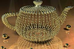
Tutorial How to Make a Dazzling Golden Pearl Teapot in 3D StudioMax
arber leka
in
Design & CAD
3
1
Intermediate
here :) follow please
Autodesk 3ds Max
studiomax
dazzling
make
how
tutorial
golden
teapot
pearl
3d
Proper Method to Produce Lobster-back Duct Bends
lawrie
in
Drafting
3
1
Beginner
One type of industrial component I have been involved with the design and manufacture of is lobster-back bends. This type of duct bend is made up of segments cut from flat sheets or plates, rolled into cylindrical parts, then assembled. These can be light sheet-metal or manufactured from thick plate. This quick tutorial is a supplement to the one I produced an outline of a method I have used modeling this type of component using Alibre Design. As this supplement concerns producing parts ready for manufacture and applies to whatever software you have used, that is not important as this short tutorial is to outline turning your modeled bend into the flat profile ready to be made into the completed bend. In this modern world, the bend parts will be cut out using CNC laser, or CNC Plasma cutting machines. Sometimes we produce the nc programs ourselves or we are required to produce the correct files for the laser / plasma department to program and cut out. Making the program to cut out the parts starts normally from a 2D dxf file at a scale of 1 : 1. This is the first part of the process that has to be correct. If you produce this dxf incorrectly the finished parts will be useless. Producing this at the right scale, 1 : 1 is different with different 3D cad applications, other problems can be caused by you working in different drawing units. If you are not doing the program, talk to the person who is to make sure you produce the dxf as required. Having a large quantity of wrongly cut parts is not a good thing
Alibre Design
Industrial Equipment Modeling 3ds max
Yağmur Medya - İsmail Ayvaz YANAR
in
Modeling
3
0
Intermediate
I wanna show how can we design an industrial equipment modeling with reference images using by 3ds max. How can we design an equipment with Reference Images ? - 3ds Max Modeling How can we design a machine with Reference Images ? Speed Modeling tutorial, Industrial Machinery and Equipment Modeling Techniques, 3ds Max industrial modeling and rendering, #industrial #modeling #3danimation
Autodesk 3ds Max
images
reference
visualization
design
rendering
modeling
3dsmax
industrial
Tutorial: how to set thickness in 3ds max
Tibor
in
Design & CAD
2
0
Beginner
STEPS
Autodesk 3ds Max
3ds
max
shell
3ds max interior design tutorial - How to use vray materials in slate material editor (part 2)
TeachLAB27
in
Modeling
2
0
Intermediate
Lesson 6 Content : - Vray material setting in slate material editor
Autodesk 3ds Max
3ds
tutorials
design
interior
tutorial
material
setting
vray
Robocon
Nauki .
in
Modeling
2
1
Beginner
number-1
Alibre Design
How to capture a 3D city model
AccuCities 3D City Models
in
Modeling
2
0
Intermediate
3D city maps are so much more than the simple evolution of paper maps. 3D city models already play a game-changing role in planning and architecture. Here are 4 most common approaches to the creation of 3D city models - 2 free options, 1 very expensive option and 1 industry-standard option.
Autodesk 3ds Max
lidar
survey
photogrammetry
twin
digital
3d
model
city
3ds max interior design tutorial (1/12) - Set up 3D layout plan with DWG
TeachLAB27
in
Modeling
2
0
Intermediate
Lesson 1 Content : How to set up 3d layout plan with dwg.file Classic option 1 : Line object and Extrude New option 2 : AEC Extended "wall"
Autodesk 3ds Max
tutorial
max
3ds
dwg
plan
layout
3d
3D Modeling of a Polar Rose Using 3DS Max - Part II
Yoana Ivanova
in
Modeling
2
0
Intermediate
MAKING THE SEEDS: 1. Creating the shape of a seed: a seeds is modeled based on a standard sphere primitive, slightly deformed with a Noise modifier to achieve a higher level of realism. 2. Applying the material to the seeds: the material applied to the seeds is intended to give them an icy effect. Resembling white pearls, they contrast against the background of the fine velvet petals. 3. Creating the material: the setting in Material Editor are shown in the figure in Step 3.
Autodesk 3ds Max
flower
polar rose
red rose
rose
seed
Cup filler machine
erick Donald
in
Modeling
2
0
Beginner
Grow stage Cup filler for Brassicas species ( seed ) #Volume fill
Autodesk 3ds Max
3ds Max Car Modelling, Surface modelling
Dimas Nugroho
in
Modeling
2
0
Beginner
https://youtu.be/errXpi0NLms https://youtu.be/stn3g_gwHcg https://youtu.be/rXVZfmqBjjg https://youtu.be/_2ipAcEq-uo
Autodesk 3ds Max
tutorial
max
3ds
modelling
3ddesign
3dsmax
car
3D Printable Threads in Alibre Atom 3D and Design Professional
Konstantinos Froudarakis
in
Modeling
2
0
Intermediate
In this tutorial you will see how to create fully formed threads for 3D printing in Alibre Atom 3D and Design Professional. If you watch it in YouTube you will also see the cards points to the video that shows the process for Alibre Design Expert.
Alibre Design
boolean
female
male
3d printing
60 degree
iso
threads
3D Modeling of a Polar Rose Using 3DS Max - Part I
Yoana Ivanova
in
Modeling
2
0
Expert
PETAL CREATION PROCESS: There are two main methods for modeling the petals as follows: 1. Surface modeling method: draw a 2D surface of suitable shape using the Create > Line tool and a volume to the surface using the Shell modifier. Edge softening is achieved with MeshSmooth modifier. 2. Using Symmetry Modifier: if we are aiming for absolute symmetry of the two halves of the petal, we must use the Symmetry, but this step must precede MeshSmooth. 3. Solid modeling method: place a standard Plane primitive in the workspace (Perspective Viewport). The desired shape is obtained by selecting and moving vertices. The remaining steps of shaping the desired form are analogous to those of the method described at the beginning of the tutorial. 4. Clone the petals: using Pivot > Affect Pivot Only, where by default the pivot point is at the center of the base of the object. In this case, a total of five rows of four petals are modeled. They mus be grouped by Group so that they do not move during further work.
Autodesk 3ds Max
flower
rose
red rose
polar rose
1
2
3
4
5