Learn about the GrabCAD Platform
Get to know GrabCAD as an open software platform for Additive Manufacturing
Visit our new homepage
Home
Control
Shop
Streamline Pro
Partner Program
Print
Community
Log in
Library
Challenges
Groups
Questions
Tutorials
Engineers
Blog
Log in
Learn from thousands of free Tutorials.
New user?
Join the community
or
log in.
Tutorials
Most liked all time
Recent
Most liked
Most viewed
Most commented
This week
This month
All time
Category
Design & CAD
Modeling
Drafting
Assemblies
BOM
Dimensioning / Tolerancing
Translations
Manufacturing & CAM
3D Printing
Tooling
NC Machining
Composites
Measurement / Inspection
Simulation & CAE
FEM
CFD
Kinematics
Process Simulation
Engineering Fundamentals
Theory
Process
Standards
Other
Software
Snagit
Alibre Design
ArchiCAD
AutoCAD
AutoCAD Electrical
Autodesk 3ds Max
Autodesk Alias
Autodesk Inventor
Autodesk Maya
Autodesk Revit
Autodesk 123D
BricsCAD
Bentley MicroStation
BlenderCAD
BobCAD-CAM
CATIA
Delmia
DraftSight
FreeCAD
Femap
Fusion 360
Geomagic Design
IronCAD
JT
Kompas-3D
KeyCreator
KeyShot
Lagoa
Luxology
Mastercam
Moi3D
NX Unigraphics
OBJ
Onshape
OpenSCAD
Parasolid
Powermill
Powershape
Pro/Engineer Wildfire
PTC Creo Parametric
PTC Creo Elements
Rhino
SpaceClaim
SOLIDWORKS
solidThinking Evolve
Solid Edge
SolidFace
STEP / IGES
SketchUp
STL
TopSolid
TinkerCAD
T-Flex CAD
TurboCAD
VectorWorks
ViaCAD 3D
VRML / WRL
ZW3D
GrabCAD Print
Rendering
GrabCAD Community
GrabCAD Workbench
Text file
3D Manufacturing Format
Cinema 4D
Other
Skill level
All levels
Beginner
Intermediate
Expert
Modeling
×
Simulation & CAE
×
Spur Gear Set - Stress Evaluation
Semih Tinmaz
in
FEM
58
0
Beginner
Spur gears have their teeth cut parallel to the axis of the shaft on which the gears are mounted, transmitting power between the parallel shafts. To maintain a constant angular velocity ratio, two meshing gears must satisfy a fundamental law of gearing: the shape of the teeth must be such that the common normal at the point of contact between two teeth must always pass through a fixed point on the line of centers. The contact point is called the pitch point. The goal is to assess the maximum stress during the transmission of the torque. By engineering judgement, the maximum stress occurs either at a contact point or at the root of a tooth due to the bending of the tooth. Since there is no restriction of deformation in the depth direction, i.e.,the gears are free to expand (or contract) in the depth direction, so it is modeled as a plane stress problem.
ansys workbench
stress analysis
transmission
gears
gear
finite element analysis
[VIDEO] SOLIDWORKS [Mold Arabic Tutorial - Plastic Product Extraction Using Direct Editing Tools]
Ahmed ElPrince
in
Modeling
57
6
Expert
Hello Everyone and Welcome.. In This Tutorial you Will Learn How to Extract a Plastic Product from any Mold Using Direct Editing Tools inside SOLIDWORKS. Also this is one of the CSWPA-MM Exam Problem Idea if You Learned S.Thing New Please Like The Video and Share it With Your Friends. Also Subscribe For Seeing More Videos Like This.
SOLIDWORKS
tricks
editing
direct
tools
mold
solidworks
Side Pole Test - High Speed Impact - Explicit Dynamics - ANSYS Workbench
Semih Tinmaz
in
FEM
54
0
Intermediate
Explicit dynamics is a time integration method used to perform dynamic simulations when speed is important. Explicit dynamics account for quickly changing conditions or discontinuous events, such as free falls, high-speed impacts, and applied loads. Because these “nonlinear dynamics” are integrated into the simulation, explicit dynamics is the preferred choice for simulating highly transient physical phenomena. Some side impacts involve a vehicle travelling sideways into rigid roadside objects such as trees or poles. Often this is the result of a loss of control on the part of the driver, owing to speeding, misjudgement of a corner or because of a skid in slippery conditions.
high-speed impact
impact
finite element analysis
explicit dynamics
ansys workbench
side pole test
crash test
How To Model Complex Sheet Metal Parts in SOLIDWORKS
Russell Everard
in
Modeling
54
9
Beginner
A step-by-step guide on how to create the shade holder part in the lamp model shown keeping cut outs in curved surfaces straight and true for a genuine flat pattern.
SOLIDWORKS
surface
curved
sheetmetal
solidworks
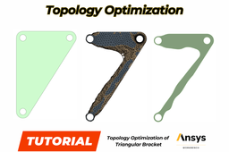
Topology Optimization of Triangular Bracket - ANSYS Workbench
Semih Tinmaz
in
FEM
53
2
Intermediate
Topology optimization is a mathematical method which spatially optimizes the distribution of material within a defined domain, by fulfilling given constraints previously established and minimizing a predefined cost function. Main aim of this tutorial is optimizing and decreasing the material density of the triangular bracket as 50% by topology optimization.
ansys workbench
ansys
spaceclaim
topology optimization
topology
How to Complete Your CAD Homework
FredSWUG
in
Modeling
52
9
Beginner
Models like this are common homework assignments for CAD students. Let's learn some skills to convert an isometric drawing into a 3D model. SOLIDWORKS is used, but these skills apply to any 3D CAD program.
SOLIDWORKS
drafting
2d
drawing
model
lesson
help
homework
solidworks
Helical Gear Shaft Tutorial
Piyush Basutkar
in
Modeling
52
13
Beginner
Hello, CAD lovers! Today we're going to learn how to make a Helical Gear Shaft. If you are new to this profile, please leave a like button on this tutorial and follow my profile for more helpful content.
CATIA
learn
tutorial
catia
shaft
gear
helical
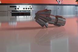
Planar Seal Simulation with Hyperelastic Experimental Data (Mooney-Rivlin Hyperelastic Model)
Semih Tinmaz
in
FEM
47
0
Intermediate
The seal which is used in the door of applications from automotive industries. The seal is a long strip of rubber and it will be modeled as a plane strain problem. A series of material tests has been conducted, including the uni-axial tensile test, the bi-axial tensile test and the shear test. A series of trials of data fitting shows that, for these material testing data, the two-parameter "Mooney-Rivlin Hyperelastic Model" fits the data better than other models. It is decided to use Two-Parameter Mooney-Rivlin Model. The unit system used in this tutorial is "U.S. Customary (in-lbm-lbf-s)".
finite element analysis
ansys workbench
mooney-rivlin model
planar seal
test
hyperelasticity
How to make a rendering with SolidWorks
Miguel De Haro
in
Modeling
46
1
Intermediate
How to make a rendering with SolidWorks
SOLIDWORKS
rendering
solidworks
Design of Radial Engine With CATIA
22255d73
in
Modeling
46
5
Expert
Radial motor design is designed as mentioned below. We open Catia and enter the part desing menu first. And from here we enter the sketch at xy from the product tree. Then we make the skeleton drawings that we are seeing below in the direction of the given meter. We record every track we make under a specific file.
CATIA
v6
catia
v5
engine
radial
Static Crack Growth Analysis of ARCAN Specimen - ANSYS Workbench
Semih Tinmaz
in
FEM
45
0
Intermediate
This tutorial includes step-by-step static crack growth analysis of ARCAN Specimen.
ansys workbench
fatigue life
fatigue crack
fracture mechanics
finite element analysis
computer aided engineering
spaceclaim
How to design a Steering Knuckle (Request)
Yahya T Khedr
in
Modeling
44
6
Beginner
==Request Tutorial== I've spent 3+ hours working on this tutorial just to show you how to design this model in SolidWorks 2016: https://grabcad.com/library/steering-knuckle-2d-to-3d-request-1 Note: The Unit system we'll use is mm.
SOLIDWORKS
car
knuckle
steering
request
modeling
solidworks
Fastest way of drawing car rims
Valentino Les
in
Modeling
43
2
Intermediate
Folow these steps to really quickly create awesome looking car rims for any car . Have on mind these rims won't match 1:1 scale because we will use pictures as references. Also these rims will only look good but won't be functional and usable for real life appliance. Only for renders. Goal of this tutorial is to create a good looking car rim as fast as possible.
SOLIDWORKS
wheel
rim
car
Seat Cowl Modeling
Xray
in
Modeling
43
2
Intermediate
I was asked how to make the my Ducati seat cowl in Catia. Unfortunately, I haven't worked in Catia for years, the model was made in Solidworks. Having worked in ProE, CATIA and Solidworks - though menu pics and verbiage may be different, they and other systems, are all capable of creating the same features with similar steps. I created a simplified PDF that shows the basic - steps taken to create this seat. These steps can be used as a frame work to design a wide variety of parts and on several CAD platforms. There are a lot of ways to do things, hopefully you find some of this useful. The model can be downloaded from GrabCAD. It is named: Ducati 996 / 998 Cafe Race Seat.
SOLIDWORKS
ducati
modeling
how
surfacing
cafe
seat
motorcycle
CATIA Course
Bramhadev Gaikwad
in
Modeling
42
4
Expert
Hello Every one, I have decided to provide catia tutorial to curious learner, Hard Working People who one always want to learn new thing .and who one is really interested to learn catia.
CATIA
defense
equipment
industrial
aerospace
automotive
1
2
3
…
100