Learn about the GrabCAD Platform
Get to know GrabCAD as an open software platform for Additive Manufacturing
Visit our new homepage
Home
Control
Shop
Streamline Pro
Partner Program
Print
Community
Log in
Library
Challenges
Groups
Questions
Tutorials
Engineers
Blog
Log in
Learn from thousands of free Tutorials.
New user?
Join the community
or
log in.
Tutorials
Most liked all time
Recent
Most liked
Most viewed
Most commented
This week
This month
All time
Category
Design & CAD
Modeling
Drafting
Assemblies
BOM
Dimensioning / Tolerancing
Translations
Manufacturing & CAM
3D Printing
Tooling
NC Machining
Composites
Measurement / Inspection
Simulation & CAE
FEM
CFD
Kinematics
Process Simulation
Engineering Fundamentals
Theory
Process
Standards
Other
Software
Snagit
Alibre Design
ArchiCAD
AutoCAD
AutoCAD Electrical
Autodesk 3ds Max
Autodesk Alias
Autodesk Inventor
Autodesk Maya
Autodesk Revit
Autodesk 123D
BricsCAD
Bentley MicroStation
BlenderCAD
BobCAD-CAM
CATIA
Delmia
DraftSight
FreeCAD
Femap
Fusion 360
Geomagic Design
IronCAD
JT
Kompas-3D
KeyCreator
KeyShot
Lagoa
Luxology
Mastercam
Moi3D
NX Unigraphics
OBJ
Onshape
OpenSCAD
Parasolid
Powermill
Powershape
Pro/Engineer Wildfire
PTC Creo Parametric
PTC Creo Elements
Rhino
SpaceClaim
SOLIDWORKS
solidThinking Evolve
Solid Edge
SolidFace
STEP / IGES
SketchUp
STL
TopSolid
TinkerCAD
T-Flex CAD
TurboCAD
VectorWorks
ViaCAD 3D
VRML / WRL
ZW3D
GrabCAD Print
Rendering
GrabCAD Community
GrabCAD Workbench
Text file
3D Manufacturing Format
Cinema 4D
Other
Skill level
All levels
Beginner
Intermediate
Expert
Autodesk Inventor
×
FreeCAD
×
Solid Edge
×
SketchUp
×
New approach in designing and modelling an Oil pump using Inventor 2016
Ebrahim Abu Has
in
Design & CAD
120
13
Intermediate
Step by step tutorial videos, showing the easy way of modelling an Oil pump using Inventor 2016, how to create the parts, assemble them and drive gears, new approach make use of most Inventor specs, design center with some new tips & tricks ...
Autodesk Inventor
ticks
tips
some
splines
parallel
shafts
keyways
keys
shaft
design
gears
spur
How to convert STL to STEP using FreeCAD
Sar Dar
in
Design & CAD
89
23
Beginner
This tutorial covers how to convert an STL to a STEP using FreeCAD. Note: Since STLs are meshes, the resulting model won't be as precise as parts originally made as solids. FreeCAD can export: - Step - Iges - Scad - Dxf - Dwg - Obj - Pdf And many others…
FreeCAD
shape
solid
conversion
iges
triangulated
mesh
convert
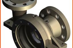
How to model a Centrifugal Pump Body (Spiral construction) using Inventor 2014?
Constantin STANCESCU
in
Design & CAD
76
18
Intermediate
We have to abide by all the conditions from the technical drawing Note: You can watch my live tutorial for modeling this part here: https://youtu.be/yxEAv2p31zw
Autodesk Inventor
centrifugal_pump
inventor_2014
ipt
multi-body
spiral
coil
LEGO - 01 Basic Dimensions & Bricks Explained
dk
in
Modeling
71
9
Intermediate
I get a lot of questions about how I create LEGO parts. This is Part I - The Basics. Most "standard" parts can be created using only simple math. Standard parts consist of square, circular, and angled blocks - regular geometric blocks. I will refer to BrickLink (www.bricklink.com/), but many others use similar methods: Peeron: http://www.peeron.com/ BrickOwl: http://www.brickowl.com/ Brickipedia: http://lego.wikia.com/wiki/LEGO_Wiki etc.
Autodesk Inventor
bricks
dimensions
lego
Cap screws and machine screws
dea
in
Drafting
69
12
Intermediate
Cap screws and machine screws are similar in shape, differing only in their relative sizes. Machine screws are usually smaller in size, compared to cap screws. These are used for fastening two parts, one with clearance hole and the other with tapped hole. The clearance of the unthreaded hole need not be shown on the drawing as its presence is obvious. Figure 5.24 shows different types of cap and machine screws, with proportions marked Cap screws are produced in finish form and are used on machines where accuracy and appearance are important. As cap screws are inferior to studs, they are used only on machines requiring few adjustments and are not suitable where frequent removal is necessary. These are produced in different diameters, upto a maximum of 100 mm and lengths 250 mm. Machine screws are produced with a naturally bright finish and are not heat treated. They are particularly adopted for screwing into thin materials and the smaller ones are threaded throughout the length. They are used in fire-arms, jigs, fixture and dies. They are produced in different diameters upto a maximum of 20 mm and lengths upto 50 mm.
Autodesk Inventor
screw
cap
How do I scale a model in Inventor?
William
in
Design & CAD
52
14
Beginner
:)
Autodesk Inventor
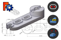
FreeCAD Basic Exercise #1
Quentin Plisson
in
Modeling
40
5
Beginner
The objective of this tutorial will be to discover the workflow for the parametric design of a 3D object with Part Design and Sketcher. For this we will model a basic part involving different types of functions.
FreeCAD
sketcher
design
part
exercise
basic
LEGO - 02 Building Bricks with Parameters
dk
in
Modeling
39
4
Intermediate
I don't get asked this but it is a very powerful tool and will make your life a lot easier. This also applies to other repetitive parts, not just LEGO bricks, and can be applied with the exact same methods.
Autodesk Inventor
parameters
lego
Tutorial: How to make energy chain and animate that by parameter
barta
in
Design & CAD
39
5
Beginner
Step by step
Autodesk Inventor
tipsntricks
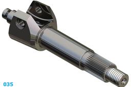
How to model a Control lever shaft using Inventor 2014?
Constantin STANCESCU
in
Design & CAD
35
8
Intermediate
If you are really interested in modeling with Inventor (2014), try to apply every step with respect to their order and watch how you reach the model. You can watch the live modeling of this part with Inventor 2021 by using this link: https://youtu.be/gOkTy_oJdH0 Enjoy!
Autodesk Inventor
[VIDEO] Bending Plate Animation Inventor 2020 Tutorial
Didi Widya Utama
in
Assemblies
35
1
Intermediate
This tutorial will show how to create a bending process of a plate in animation, hope this video will give you clear explanation. please leave comment below
Autodesk Inventor
studio
animation
plate
bending
tutorial
2020
inventor
autodesk
FreeCAD Basic Exercise #5
Quentin Plisson
in
Modeling
35
2
Beginner
This tutorial allows you to discover new Additive tools in FreeCAD Part Design workbench: Additive loft and Revolution. It also introduces the notion of Datum object to create new reference elements in a part.
FreeCAD
datum
exercise
basic
revolution
loft
open-source
additive
Modelling of Impeller
Mohit
in
Design & CAD
29
4
Beginner
Modelling of Impeller
Autodesk Inventor
cad
model
centrifugal
parts
pump
impeller
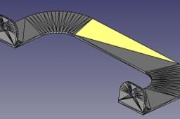
How to model a curved spring
Jens Nielsen
in
Modeling
27
8
Intermediate
Let me show you how to use some surface commands which combine in a 3Dsketch for the solid sweep. No coil command needed. on youtube at: https://youtu.be/wcB5OBTrqfA
Autodesk Inventor
coil
3dintersection
surface
sweep
spring
FreeCAD Basic Exercise #3
Quentin Plisson
in
Modeling
27
4
Beginner
The objective of this tutorial will be to hang external geometry with the Circle and Polyline tools. Use the Linear Pattern function and use a subtractive function (Pocket) from a face.
FreeCAD
basic
polyline
slot
circle
geometry
external
pattern
linear
1
2
3
…
100