Learn about the GrabCAD Platform
Get to know GrabCAD as an open software platform for Additive Manufacturing
Visit our new homepage
Home
Control
Shop
Streamline Pro
Partner Program
Print
Community
Log in
Library
Challenges
Groups
Questions
Tutorials
Engineers
Blog
Log in
Learn from thousands of free Tutorials.
New user?
Join the community
or
log in.
Tutorials
Most liked all time
Recent
Most liked
Most viewed
Most commented
This week
This month
All time
Category
Design & CAD
Modeling
Drafting
Assemblies
BOM
Dimensioning / Tolerancing
Translations
Manufacturing & CAM
3D Printing
Tooling
NC Machining
Composites
Measurement / Inspection
Simulation & CAE
FEM
CFD
Kinematics
Process Simulation
Engineering Fundamentals
Theory
Process
Standards
Other
Software
Snagit
Alibre Design
ArchiCAD
AutoCAD
AutoCAD Electrical
Autodesk 3ds Max
Autodesk Alias
Autodesk Inventor
Autodesk Maya
Autodesk Revit
Autodesk 123D
BricsCAD
Bentley MicroStation
BlenderCAD
BobCAD-CAM
CATIA
Delmia
DraftSight
FreeCAD
Femap
Fusion 360
Geomagic Design
IronCAD
JT
Kompas-3D
KeyCreator
KeyShot
Lagoa
Luxology
Mastercam
Moi3D
NX Unigraphics
OBJ
Onshape
OpenSCAD
Parasolid
Powermill
Powershape
Pro/Engineer Wildfire
PTC Creo Parametric
PTC Creo Elements
Rhino
SpaceClaim
SOLIDWORKS
solidThinking Evolve
Solid Edge
SolidFace
STEP / IGES
SketchUp
STL
TopSolid
TinkerCAD
T-Flex CAD
TurboCAD
VectorWorks
ViaCAD 3D
VRML / WRL
ZW3D
GrabCAD Print
Rendering
GrabCAD Community
GrabCAD Workbench
Text file
3D Manufacturing Format
Cinema 4D
Other
Intermediate
All levels
Beginner
Intermediate
Expert
Modeling
×
FEM
×
Process Simulation
×
How to design Complete Drone Overview
Rugved Chavan
in
Modeling
91
9
Intermediate
Complete Drone design with 1. raspberry pi 4 extension 2. pixhawk 3. landing gears 4. drone frame 5. telemetry module 6. gps module with stand 7. Battery 3300 mAh 8. antivibrator 9. Brushless Motor (BR4114) Please give it a like.
Fusion 360
fusion360
telemetry
raspberrypi
drone
Fatigue Crack Growth Analysis of Modified Compact-Tension Specimen - ANSYS Workbench
Semih Tinmaz
in
FEM
84
15
Intermediate
This tutorial includes step-by-step fatigue crack analysis of Modified Compact-Tension Specimen.
spaceclaim
computer aided engineering
finite element analysis
fracture mechanics
paris law
ansys workbench
fatigue crack
fatigue life
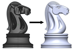
Convert STL (or OBJ) Mesh to SOLIDWORKS Model (NURBS)
FredSWUG
in
Modeling
72
12
Intermediate
Need to convert an STL (or OBJ) file into a "real CAD model"? There are several tutorials which already exists for this topic. I'm making a new tutorial to give additional information.
SOLIDWORKS
part
convert
model
sldprt
mesh
stl
LEGO - 01 Basic Dimensions & Bricks Explained
dk
in
Modeling
71
9
Intermediate
I get a lot of questions about how I create LEGO parts. This is Part I - The Basics. Most "standard" parts can be created using only simple math. Standard parts consist of square, circular, and angled blocks - regular geometric blocks. I will refer to BrickLink (www.bricklink.com/), but many others use similar methods: Peeron: http://www.peeron.com/ BrickOwl: http://www.brickowl.com/ Brickipedia: http://lego.wikia.com/wiki/LEGO_Wiki etc.
Autodesk Inventor
bricks
dimensions
lego
SOLIDWORKS TUTORIAL : DESIGN A NISSAN GTR.
Rare Mechanic
in
Modeling
62
4
Intermediate
Hey designer, Hope you going well in your designing Journey. I've made a complete step by step tutorial in which you're going to design a 'NISSAN GTR" in solidworks. . Start this tutorial series & enhanced your surfacing skills by completing it.
SOLIDWORKS
tutorial
cardesigning
advancedsurfacing
solidworkstutorial
design
nissangtr
automobile
cad
Side Pole Test - High Speed Impact - Explicit Dynamics - ANSYS Workbench
Semih Tinmaz
in
FEM
54
0
Intermediate
Explicit dynamics is a time integration method used to perform dynamic simulations when speed is important. Explicit dynamics account for quickly changing conditions or discontinuous events, such as free falls, high-speed impacts, and applied loads. Because these “nonlinear dynamics” are integrated into the simulation, explicit dynamics is the preferred choice for simulating highly transient physical phenomena. Some side impacts involve a vehicle travelling sideways into rigid roadside objects such as trees or poles. Often this is the result of a loss of control on the part of the driver, owing to speeding, misjudgement of a corner or because of a skid in slippery conditions.
high-speed impact
impact
finite element analysis
explicit dynamics
ansys workbench
side pole test
crash test
Topology Optimization of Triangular Bracket - ANSYS Workbench
Semih Tinmaz
in
FEM
53
2
Intermediate
Topology optimization is a mathematical method which spatially optimizes the distribution of material within a defined domain, by fulfilling given constraints previously established and minimizing a predefined cost function. Main aim of this tutorial is optimizing and decreasing the material density of the triangular bracket as 50% by topology optimization.
ansys workbench
ansys
spaceclaim
topology optimization
topology
Planar Seal Simulation with Hyperelastic Experimental Data (Mooney-Rivlin Hyperelastic Model)
Semih Tinmaz
in
FEM
47
0
Intermediate
The seal which is used in the door of applications from automotive industries. The seal is a long strip of rubber and it will be modeled as a plane strain problem. A series of material tests has been conducted, including the uni-axial tensile test, the bi-axial tensile test and the shear test. A series of trials of data fitting shows that, for these material testing data, the two-parameter "Mooney-Rivlin Hyperelastic Model" fits the data better than other models. It is decided to use Two-Parameter Mooney-Rivlin Model. The unit system used in this tutorial is "U.S. Customary (in-lbm-lbf-s)".
finite element analysis
ansys workbench
mooney-rivlin model
planar seal
test
hyperelasticity
How to make a rendering with SolidWorks
Miguel De Haro
in
Modeling
46
1
Intermediate
How to make a rendering with SolidWorks
SOLIDWORKS
rendering
solidworks
Static Crack Growth Analysis of ARCAN Specimen - ANSYS Workbench
Semih Tinmaz
in
FEM
45
0
Intermediate
This tutorial includes step-by-step static crack growth analysis of ARCAN Specimen.
ansys workbench
fatigue life
fatigue crack
fracture mechanics
finite element analysis
computer aided engineering
spaceclaim
Fastest way of drawing car rims
Valentino Les
in
Modeling
43
2
Intermediate
Folow these steps to really quickly create awesome looking car rims for any car . Have on mind these rims won't match 1:1 scale because we will use pictures as references. Also these rims will only look good but won't be functional and usable for real life appliance. Only for renders. Goal of this tutorial is to create a good looking car rim as fast as possible.
SOLIDWORKS
wheel
rim
car
Seat Cowl Modeling
Xray
in
Modeling
43
2
Intermediate
I was asked how to make the my Ducati seat cowl in Catia. Unfortunately, I haven't worked in Catia for years, the model was made in Solidworks. Having worked in ProE, CATIA and Solidworks - though menu pics and verbiage may be different, they and other systems, are all capable of creating the same features with similar steps. I created a simplified PDF that shows the basic - steps taken to create this seat. These steps can be used as a frame work to design a wide variety of parts and on several CAD platforms. There are a lot of ways to do things, hopefully you find some of this useful. The model can be downloaded from GrabCAD. It is named: Ducati 996 / 998 Cafe Race Seat.
SOLIDWORKS
ducati
modeling
how
surfacing
cafe
seat
motorcycle
Solidworks Car Tutorial :Model a NISSAN GTR.
H.J. Bhatt
in
Modeling
42
0
Intermediate
Hey designer, Hope you going well in your designing Journey. I've made a complete step by step tutorial in which you're going to design a 'NISSAN GTR" in solidworks. . Start this tutorial series & enhanced your surfacing skills by completing it.
SOLIDWORKS
solidworks
advancedsurfacing
tutorial
automobile
cad
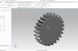
How to create spur gear in Siemens NX?
Hegedűs György
in
Modeling
41
6
Intermediate
This tutorial presents the modeling of an external spur gear in Siemens NX. The detailed modeling process is demonstrated on this video: https://youtu.be/pVPjDyOn6R4 UPDATE: At ~ 2:40 leave the Limit options at default (At Point). See the errata video for the reason: https://youtu.be/PUpdlyQcaOs
NX Unigraphics
gear
spur
Chassis Design Using CATIA
Jasper Aaron
in
Modeling
39
1
Intermediate
Chassis Design using CATIA Wireframe > Surface > Solid
CATIA
surface
frame
car
model
supra
advanced
tutorials
modelling
rollcage
catia
using
design
chassis
1
2
3
…
100