

Tutorial how to make engine part 1

I will generate tutorials that explains how to make car engine step by step
I used random dimensions. I want to explain the commands and the way to make an engine. You can use your dimensions
In this part we will start with connecting rod
part 1: http://grabcad.com/questions/tutorial-how-to-make-engine-part-1
part 2: http://grabcad.com/questions/tutorial-how-to-make-engine-part-2--1
part 3: http://grabcad.com/questions/tutorial-how-to-make-engine-part-3
part 4: http://grabcad.com/questions/tutorial-how-to-make-engine-part-4
part 5: http://grabcad.com/questions/tutorial-how-to-make-engine-part-5
part 6: http://grabcad.com/questions/tutorial-how-to-make-engine-part-6
part 7: http://grabcad.com/questions/tutorial-how-to-make-engine-part-7
part 8: http://grabcad.com/questions/tutorial-how-to-make-engine-part-8
part 9: http://grabcad.com/questions/tutorial-how-to-make-engine-part-9
part 10: http://grabcad.com/questions/tutorial-how-to-make-engine-part-10
part 11: http://grabcad.com/questions/tutorial-how-to-make-engine-part-11
part 12: http://grabcad.com/questions/tutorial-how-to-make-engine-part-12
part 13: http://grabcad.com/questions/tutorial-how-to-make-engine-part-13
part 14: http://grabcad.com/questions/tutorial-how-to-make-engine-part-14
part 15: http://grabcad.com/questions/tutorial-how-to-make-engine-part-15
part 16: http://grabcad.com/questions/tutorial-how-to-make-engine-part-16
part 17: http://grabcad.com/questions/tutorial-how-to-make-engine-part-17
part 18: http://grabcad.com/questions/tutorial-how-to-make-engine-part-18
part 19: http://grabcad.com/questions/tutorial-how-to-make-engine-part-19
part 20: http://grabcad.com/questions/tutorial-how-to-make-engine-part-20
part 21: http://grabcad.com/questions/tutorial-how-to-make-engine-part-21
part 22: http://grabcad.com/questions/tutorial-how-to-make-engine-part-22
part 23: http://grabcad.com/questions/tutorial-how-to-make-engine-part-23
part 24: http://grabcad.com/questions/tutorial-how-to-make-engine-part-24
part 25: http://grabcad.com/questions/tutorial-how-to-make-engine-part-25
part 26: http://grabcad.com/questions/tutorial-how-to-make-engine-part-26
semi final: http://grabcad.com/questions/tutorial-how-to-make-engine-final
part 27: http://grabcad.com/questions/tutorial-how-to-make-engine-part-27
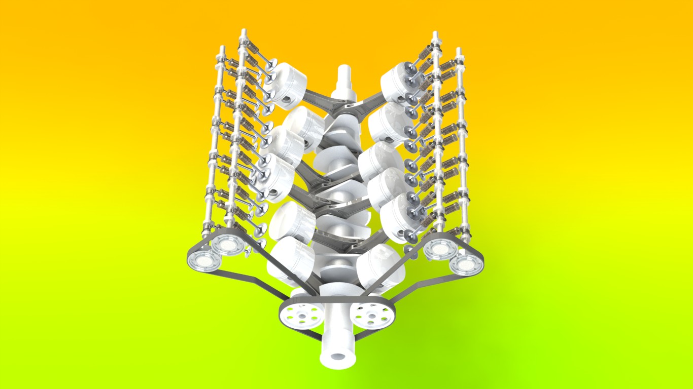
FILE: V12 engine
semi final http://grabcad.com/questions/tutorial-how-to-make-engine-part-27
cylinder head http://grabcad.com/questions/tutorial-how-to-make-engine-part-28
cylinder head http://grabcad.com/questions/tutorial-how-to-make-engine-part-29
cylinder head http://grabcad.com/questions/tutorial-how-to-make-engine-part-30
cylinder head http://grabcad.com/questions/tutorial-how-to-make-engine-part-31
cylinder head http://grabcad.com/questions/tutorial-how-to-make-engine-part-32
cylinder head http://grabcad.com/questions/tutorial-how-to-make-engine-part-33
cylinder head http://grabcad.com/questions/tutorial-how-to-make-engine-part-34
cylinder head http://grabcad.com/questions/tutorial-how-to-make-engine-part-35
cylinder head http://grabcad.com/questions/tutorial-how-to-make-engine-part-36
camshaft http://grabcad.com/questions/tutorial-how-to-make-engine-part-37
camshaft http://grabcad.com/questions/tutorial-how-to-make-engine-part-38
valve seat, right side http://grabcad.com/questions/tutorial-how-to-make-engine-part-39
retainer, valve seat http://grabcad.com/questions/tutorial-how-to-make-engine-part-40
valve nails http://grabcad.com/questions/tutorial-how-to-make-engine-part-41
intake valve http://grabcad.com/questions/tutorial-how-to-make-engine-part-42
exhaust valve, springs http://grabcad.com/questions/tutorial-how-to-make-engine-part-43
springs http://grabcad.com/questions/tutorial-how-to-make-engine-part-44
springs http://grabcad.com/questions/tutorial-how-to-make-engine-part-45
spag plug http://grabcad.com/questions/tutorial-how-to-make-engine-part-46
spag plug http://grabcad.com/questions/tutorial-how-to-make-engine-part-47
spag plug http://grabcad.com/questions/tutorial-how-to-make-engine-part-48
 large.jpg
 large_(1).jpg
 large_(2).jpg
 large_(3).jpg
 render_2.JPG
 render_6.JPG
 render_7.JPG
 render_8.JPG
 render5.JPG
112 Answers
Connecting Rod
file: connecting rod
Answered with a tutorial: https://grabcad.com/tutorials/tutorial-how-to-make-engine-part-1
New tutorials will be published next month!
Start to modelling your V12!
Answered with a tutorial: https://grabcad.com/tutorials/tutorial-how-to-make-engine-part-1--1

That would be really helpful if you continue the tutorial on how to make engine.
Thanks Aykut!

Dear all one thing I can not understand here you have drawn one hole worth 5 mm here after than you have drawn 7mm hole and both the holes has been extrude cut through out from their so you have shown both holes in drawings so how it is possible??

i really thank you for this

very good


The tutorial is really helpful.
How come is the extrude of 11mm and in the drawing it shows thickness = 15mm ? Other than that , thank you very much... I'm using this to get some knowledge about combustion motors as I'll be introduced to them in a couple months in thermodynamics II.

Hello aykut, are there any drawing files of the dimensions?
can you upload them too... that would be very helpful for us to follow up with the dimensions.... I want to make an engine.
Thank you

very helpful tutorial indeed! thanks!
This tutorial is very well, If you are coaching o are learning
Thanks for your contributions

GOOD
very good
How to make a water gun

The tutorial was really helpful. I am looking forward for more of this

thanks

Helpful & quite easy to understand . Thanx for ur Contributions

Very good tutorial. Part 1 is ready, I'll carry on right away. Thank You Aykut Danak.
it's very useful to me as learning this software.
thank you.
please upload it as video tutorial.
Thanks in advance!

Thanks Aykut! It's very useful...

this part have problem,e drawing does not equal to your part!!!!!please check it!!!!(if you sketch it,you can understand what i mean)

Props to the tutor. Gret tutorial!!. I look forward to the day when I can share one with fellow students of solidworks. Thanks
As I see these tutorials can help another cad solfware users
Kaushal Bhatt created his own V12 on CATIA!
Detailed tutorial! Thank you. I'll follow the rest tutorials.

awesome tutorial...........

I'm just finish your model
it is too good
Its so awesome and extremely helpful for engineering study................again thanks....

Great Job, Looks like a lot of fun.
I'll start on this tonight...

Thanks. It's very helpful

its very helpful .thankz ..i like ur site
Very nice tutorial so far after i enjoyed creating the first part, I assume the last fillet around the edge of the connecting rod was 0.5mm? that's what i used
how to make tangent lines between two circles in solidworks 2010?
The filleting part is confusing.
The given file mentions something else compared to the tutorial...
Corrections to that section would make it easier =)
Great job on the tutorial (Y)

nice tuto, in step 6 when i try to fillet , the system tell me its not possible becouse specified radius would eliminate one of the elements.
some know how to resolve, thanks
fernando

Helpful & quite easy to understand . Thanx for ur Contributions

one question to inventor users,when the crank has been built you can go in and turn the journals to the degs that they need to be,now you cant do that in inventor unless you made one piece and brought it in to the assembly files,any other way of doing it or should I just model the crank in a part file and make the changes there so its all one solid,ie just do it by constraining the sketch in the first place,built the whole crank and then found I could not change the angles in the part file or can I???

wow,it amazing,just that i can say
Allah razı olsun kardeşim. ben kimya mühendisiyim, hobi olarak uğraşıyorum Solid ile.
Böyle uluslararası platformlarda sizin gibi yetenekli kardeşlerimizi görünce gurur duymamak içten değil.
İnşallah ben de çizmeyi deneyeceğim bu parçayı...

assembly of valves ,springs and cams
It is amazing .I will save it for future study.

First of all big thanks for this extraordinary tutorial, it helps me my graduated project. Now I would like type a couple of turkish words.
abii eyvallah :))

very helpful..thank you.
Very nice and helpful work. Thanks!
Awesome and well explained tutorial!!!
Gracias.

thanks .....

good

thanks

thanks , it's very useful,

thanks

thanks ..it is an easy step ^^

A lot of thanks to you
Thank you for all of this tutorials. I'll try to all understand but that's not quite simple as I'm a french personn. I imagine there a not tutorials in french. Don' worry I better understand than I write :D

well done! awesome work!
Well done and God bless you.

very good but I miss the distance of 5 mm diameter hole

thanks for your advice very helpful !!!

Thanks Aykut. The tutorial is pretty helpful. I made an Alibre Design version of this connecting rod.

Thank you for your tutorial ;) !
Superb tutorial! Congrats!

vary halpful & easy for designing my second car engine
Well done Aykut. Very detailed tutorial. I am encouraging you to prepare other tutorials for Sheet Metal an for Welding for example.. Congrats !!!
i didn't understand the step 12. i can't intersect the lines.

Very detailed and helpful this tutorial.
Thank you !!!
These tutorials look great and are detailed. Btw would you happen to know where I can find detailed dimensions for engine parts so that I can accurately model them?

very good, halpful I will finish it

Hello, very happy I have found this tutorial, thanks.
I done everything for this one apart from somewhere between step 12 & 13 where I cannot figure out how to mirror the groove shape into the opposite side?
Any help would be great...thanks.

nice

this is perfect in the line of STEM work I do with kids, I already have them using SolidWorks to model a Formula Lego Car, the engine tutorial will completely blow their mind to the power of CAD!
wonderful, many thanks
First of all Hi!My name is George and i have to say that i am newbie with solidworks so i have some questions. Why my sketch brings out some yellow lines when i trim in step 5 and 7?I do exactly what you show but i still get this lines. I do it over and over and the yellow lines is still there.i dont know if i dont do something right but i rly wanna do this tutorial.i cannot extrude and i believe this is from the yellow lines..i get an error that says "sketch contains more than one open contour"......... Plz any help it would be great. P.S.1. I get this yellow lines in tangents. P.S.2. I am from greece so i am sry about my bad english.
First of all Hi!My name is George and i have to say that i am newbie with solidworks so i have some questions. Why my sketch brings out some yellow lines when i trim in step 5 and 7?I do exactly what you show but i still get this lines. I do it over and over and the yellow lines is still there.i dont know if i dont do something right but i rly wanna do this tutorial.i cannot extrude and i believe this is from the yellow lines..i get an error that says "sketch contains more than one open contour"......... Plz any help it would be great. P.S.1. I get this yellow lines in tangents. P.S.2. I am from greece so i am sry about my bad english.
Hey, I'm doing this in AutoCAD 2013, and I can't seem to figure out Step 6 for the Fillet. I'm new to AutoCAD so if anybody could please tell me how to do that step I would be very grateful, Thanks.

Aykut kardeş mükemmel paylaşım..Teşekkürler

THE 5 MM HOLES ON THE BOTTOM GO THRU, BUT THE 6.5 MM HOLES STOP SHORT OF GOING THRU.

can u pls give some source where i can find real standard dimensions of all engine parts used practically somewhere...i badly need them to work on a designing project

nice
very good
Thanks its a great Job

great

it's very nice work,of course I can use solidwork ,but I do not know engine knowlege,I want to study it

help me to made cnc 5 axis,please

can anyone tell me what is the value of the fillets on steps 6 and 8?
This tutorial is very helpful and has given me a lot more knowledge and understanding of solidworks as a beginner.

Nice post
Great very helpful..........Thanks.

in the drawing you can use its
symmetrical entities easier
Thank you !

wow v12, great thank you for sharing!!

Wow! You are very nice,thank you for sharing the knowledge,this is very usefull!!

Very nice
why in the tutorial two holes drawn with different diameter andboth the holes has been extrude cut ?!!!
Nicely done bro, just wanted to know can u upload all Images of tutorials at once as an pdf or book i will be better in a way to download and perform applications with a printed hand book. And thanks for the uploads.
thanks

how can we draw fillet at step 6.ı cant do this.please help me

could u please giv methe cad draftig of each parts with dimension?
What is this link?

can you provide tutorial in testing this engine via simulations

please share of eBook for it.?
I want to get it
This tutorial is godlike
can u please post these in PDF format (if possible) so we can download and work offline

Don't bother building this engine if you ever want to fully complete it! The tutorial is incomplete and stops at step 49 basically leaving you with the bottom end and the cylinder heads. You can design the rest yourself if you feel capable but don't rely on Aykut Dana (the tutorial maker) for any assistance as he will ignore any and all contact!
How do you open the file?????
Where's the tutorial?
Wow, this is really good!

wooo

Can anyone tell me where is the drawing file?
